
Operating instructions
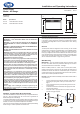

Dimensions
(millimetres)
Installation and Operating Instructions
Panel Heater
Model : NP Range
INCCUK35RG Issue 1
Model Specication
NP 150 1.5 kW Mains Neon Indicator
NP 200 2.0 kW Mains Neon Indicator
IMPORTANT : THESE INSTRUCTIONS SHOULD BE READ CAREFULLY AND RETAINED FOR FUTURE REFERENCE
Important Safety Advice
WARNING – THIS APPLIANCE MUST NOT BE USED IN A
BATHROOM.
WARNING - DO NOT USE THIS HEATER IN THE IMMEDIATE
SURROUNDINGS OF A BATH, A SHOWER OR A SWIMMING
POOL.
WARNING – THIS HEATER MUST NOT BE LOCATED IMMEDIATELY
BELOW A FIXED SOCKET OUTLET.
DO NOT USE THE HEATER UNTIL THE WALL BRACKET IS FITTED
CORRECTLY.
WARNING: This heater is not equipped with a device to control the
room temperature. Do not use this heater in small rooms when
they are occupied by persons not capable of leaving the room on
their own, unless constant supervision is provided.
FOLLOW these instructions carefully.
NEVER cover or obstruct in any way the heat outlet slots at the top
of the heater or the air inlet slots in the base of the heater.
The heater carries a warning ‘DO NOT COVER’ to alert the user to
theriskofrethatexistsiftheheaterisaccidentallycovered.
Warning: Due care and consideration must be taken when using
this heater in series with a thermal control, a program controller, a
timer or any other device that switches on the heater automatically,
sinceareriskexistswhentheheaterisaccidenticallycovered
or displaced.
This appliance is not intended for use by persons (including
children) with reduced physical, sensory or mental capabilities, or
lackofexperienceandknowledge,unlesstheyhavebeengiven
supervision or instruction concerning use of the appliance by a
person responsible for their safety. Children should be supervised
to ensure that they do not play with the appliance.
If young children, the aged or inrm are likely to be left in the
vicinity of the heater, we advise that adequate precautions should
betaken.Werecommendthataguardbettedtoensurecontact
with the heater is avoided and objects cannot be inserted into the
product.
If the supply cord is damaged, it must be replaced by the
manufacturer,itsserviceagentorasimilarlyqualiedpersonin
order to avoid a hazard.
Electrical
WARNING – THIS APPLIANCE MUST BE EARTHED
The electrical installation must be carried out by a competent electrician,
and be in strict accordance with the current I.E.E. regulations for
Electrical Equipment in Buildings.
The heater is tted with a length of exible cable type H05VV-F size 3
x 1.0mm
2
for connection to the xed wiring of the premises through a
suitable connection box positioned adjacent to the heater.
The supply circuit to the heater must incorporate a double pole isolating
switch having a contact separation of at least 3mm.
Supplementary Earth Bonding
Should Equipotential Earth Bonding be required the earthing conductor
in the supply cord is deemed to provide the supplementary bonding
connection (See Regulation 544.2.5, latest edition I.E.E. Wiring
Regulations).
General
The NP panel heater is designed for wall mounting on the bracket
supplied and it should only be operated when in the installed position
as shown in Fig. 1 above. Before connecting the heater check that
the supply voltage is the same as that stated on the heater. The mains
neon indicator will glow to show when the heater is connected to the
mains supply. The NP panel heater has no controls and is operated
with an external thermostatic or programming controller.
Wall Mounting
IMPORTANT – The wall bracket supplied with the appliance must
be used. The heater should be positioned observing the minimum
clearances stated around the heater - see Fig. 1.
Select a suitable position on a wall, near to a mains power socket,
making sure that there is at least 230 mm below the heater and at
least 450 mm above the heater of unobstructed space. Ensure that
curtains and furniture are not positioned close to the chosen position,
as this would create a potential re hazard.
DO NOT locate the heater immediately below a xed socket outlet or
connection box.
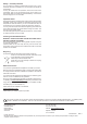
1. Remove wall mounting bracket from the back of the heater by
depressing the spring latch at the top of each bracket - see
Fig. 2.
2. Fix the wall bracket securely to the wall through the four screw
holes provided.
3. Present the heater to the wall bracket, and engage lower slots
inthe back with bracket.
4. Raise the heater to upright position and push the heater onto
brackets to engage top latch.
Fig. 2
Fig. 1
312
MIN
184
580
230
575
MIN
230
450
350
MIN
MIN