
User's Manual


2
3. Installation
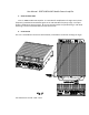
Install the unit in one of two positions, showed at the right side of Fig. 2: vertical or horizontal.
The proper air access to the unit shall be provided: no obstacle for air is allowed closer than 3”
from heatsink. Also, make sure that status LED can be monitored.
Screws from # 10 to # 1/4-20 are recommended. See the fastening holes positions in Fig. 3.
Use copper wires # 10 AWG shall be used for connecting to clamps “+ BATT” and “GND”. Use
copper wire from # 16 AWG to # 12 may by used for connecting to clamp “+ IGNITION”. Wires
shall be crimped for making ring terminals.
Connect the clamp “GND” to the car nearest ground screw of suitable size.
Connect the clamp “+ BATT” to the pole “+” of car battery. Use 30 A fuse for protection.
Connect the clamp “+ IGNITION” to the output of car ignition key that is able to provide not less
than 8 V and not less than 3 mA when it is keyed on. Use 0.5 A fuse for protection.
Use 50 Ohm coax cables with THC (M) connectors for connecting to “XCVR” and “ANT” .
Connect the port “XCVR” to RF output of radio.
Connect the port “ANT” to antenna.
4. Operation
- LED “DC” goes on continuously, when the car ignition key is ON position;
- LED “TX” goes on continuously, when the RF input power is greater ~1/3 of minimum
rated level (see Table 1);
- The continuous transmit time should not exceed 2 min, and the duty cycle should not be
greater than 25% to avoiding overheating;
- In the case of overheating (the heatsink temperature reaches +85ºC) the unit switches to
RX mode, and LED “DC” starts flashing (independently of input power);
- If the load VSWR exceeds 2-3:1, the output power reduces, and LED “DC” starts flashing,
when RF signal is applied to the input.'