INSTALLATION AND OPERATING MANUAL P25 Series UHF CONTINUOUS DUTY POWER AMPLIFIER Crescend Technologies 140 E. State Parkway Schaumburg, IL 60173 Tel: 847-908-5400 Fax: 847-908-5408 sales@crescendtech.com www.crescendtech.
User Manual 040003A010 Rev A Page 2 of 25
User Manual 1 GENERAL DESCRIPTION 1.1 INTRODUCTION This manual contains installation and operating information for the Crescend High Power 406-420 MHz Power Amplifier. The manual is organized into multiple sections as follows: 1 2 3 4 5 6 GENERAL DESCRIPTION .................................................................................................................... 3 1.1 INTRODUCTION ..........................................................................................................
User Manual GA amplifiers cover the 406-420 MHz band without retuning. Model HA amplifiers cover the 450470MHz band without retuning. Amplifier specifications are shown in Table 1-1. There are seven input ranges available as shown in Table 1-2. Closed loop power control is used to maintain a constant output power under varying voltage, signal input level, frequency and output load conditions. Several design features work to protect the amplifier under adverse conditions.
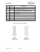
User Manual 2 INSTALLATION 2.1 INSTALLATION INSTRUCTIONS The amplifier is designed for installation in a rack that permits access to the rear of the unit for connection of RF and monitor/control cables, and DC power cables or AC line cord if the unit incorporates the internal AC power supply option. The amplifier must have a minimum of 3 inches of open space in front and to the rear of the chassis to allow adequate air flow and ventilation.
User Manual negative primary power wire to GND terminal next to it on rear of amplifier. 7. Check your work before applying DC voltage to the system. Make certain all connections are tight and the DC wires are going to the correct terminals. 8. If the unit has the optional internal AC power supply: Connect an unpowered AC cord to AC plug on rear of amplifier. 9. Refer to Section 2.2 for initial start-up procedures. 2.2 INITIAL STARTUP To perform the initial start-up, proceed as follows: 1.
User Manual 3 OPERATING INFORMATION 3.1 INTRODUCTION This section contains general amplifier operating information 3.2 STATUS INDICATORS AND MONITOR CONNECTOR The amplifier status indicators and alarms are described in Table 3-1 and Table 3-2. Table 3-1 High Power UHF Amplifier Status LED Indicators STATUS LED FUNCTION PWR ON Green LED. Illumination indicates unit is powered on EXCITER DRIVE Green LED. Illumination indicates RF input power has been applied CHECK FAN Red LED.
User Manual PIN NO NAME DESCRIPTION 7 HI INPUT 8 CHECK FAN 9 PA FAULT Alarm - Low Output Power, RF Input Power Above Maximum Rating, High Temperature Amplifier Shutdown, High VSWR or No Power Supply Voltage 10 FWD PWR Forward Power Voltage 11 HI VSWR Alarm - High VSWR 12 RF DRIVE Minimum RF Input Drive Indicator 13 TXD RS232 Interface Transmitted Data 14 GND NOT FOR EXTERNAL CONNECTION - DO NOT USE 15 LOW PWR Alarm - RF Input Power Above Maximum Rating Alarm - Low fan speed or lo
User Manual 3.3 DETAILED STATUS INDICATOR AND MONITOR CONNECTOR INFORMATION The detailed amplifier status indicators, alarm truth table and monitor connector information is described in detail in Table 3-3 through Table 3-5. Table 3-3 Amplifier Status Indicators LED NAME FUNCTION PWR ON DC Power Up Indicator EXCITER DRIVE INDICATION CONDITION Green Light Power is turned on Off Power is turned off Green Light RF input power is at or above threshold.
User Manual Table 3-4 Alarm Truth Table Alarm LED Color Amplifier Shutdown PA Fault Recovery CHECK FAN Red No High Clean fans, replace if defective HI TEMP Red Yes High Reduce PA temperature below 65°C HI VSWR Red Yes High Input Re-Key HI INPUT Yellow No High Input Re-Key LOW OUTPUT Yellow No High Set input drive above minimum threshold Table 3-5 Monitor Connector Description PIN NO 1. 2. 3. 4.
User Manual PIN NO 7 8. NAME SIGNAL DESCRIPTION TYPE HI INPUT Dig CHECK FAN Dig Alarm – High Input Power Detected at Amplifier Input SIGNAL STATES CONDITION <0.8V Alarm – RF input power exceeds maximum power threshold level. To reset the alarm, it is necessary to reduce RF drive signal level and reapply RF input power (The alarm will remain illuminated after RF input power is removed) >3.3V Normal Operation <0.8V Alarm – Low fan speed or locked rotor detected.
User Manual PIN NO 15. NAME LOW PWR SIGNAL DESCRIPTION TYPE Digital Output Alarm - Low Output Power SIGNAL STATES CONDITION <0.8V Alarm – the analog control loop is open and unable to adjust the output power level. Alarm is turned off only when the analog control loop is closed. Check if drive level is within normal limits. If RF input is within range, and all other conditions are normal, this may indicate a potential PA failure. >3.
User Manual 3.4 DIGITAL COMMUNICATION INTERFACE (RS232) The amplifier is supplied with a RS232 digital communication interface that provides status and alarm information. The communications interface settings are described in detail in Table 3-6. Table 3-6 Digital Communication Interface Settings Voltage Level RS232 voltage levels Transmission Bit Rates 38.
User Manual COMMAND RETURNED ANSWER NOTES “RT?\r” “RT=***C” Return active stage temperature. Examples: “RT=095C”, “RT=-09C” “RV?\r” “RV=**.***V\r” Return DC supply voltage. Example: RV=47.985V “RC?\r” “RC=**.***A\r” Return DC supply current. Current does not include fan current. Example: “RC=09.233A\r” “EX=1\r” “EX=1\r” Enable the external control of output power level.
User Manual COMMAND RETURNED ANSWER NOTES "PM?\r" "PM=***W\r" Return power level that is saved in nonvolatile memory. If the external control of output power level is enabled, the amplifier returns “EX” value. Example: “PM=250W\r” “PM=EX\r” "CF?\r" “CF=1\r” Return CHECK FAN alarm status. (0 - alarm; 1 - normal operation) "F1?\r" “F1=*****RPM\r” Return fan 1 speed. Example: “F1=03450RPM\r” "F2?\r" “F2=*****RPM\r” Return fan 2 speed. Example: “F2=03500RPM\r” "FT?\r" “FT=*****RPM\r” Example:
User Manual COMMAND RETURNED ANSWER NOTES “ED?\r” “ED=*\r” Return EXCITER DRIVE condition state. Example: (0 - RF input signal present; 1 - no RF signal at PA input) “ED=0\r” * - represents a single char 040003A010 Rev A Page 16 of 25
User Manual 3.5 POWER SET CONTROL The amplifier is equipped with a single turn POWER SET potentiometer located on the front panel. The potentiometer allows the user to adjust the amplifier output power from 250W down to 25W. Turning the potentiometer fully clockwise sets the amplifier to the maximum output power level. POWER SET potentiometer pulls down the POWER CTL signal located in the Monitor connector (section 3.2 and 3.3).
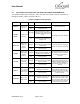
User Manual 4 TROUBLESHOOTING 4.1 INTRODUCTION This section contains a list of potential problems and suggested actions to be taken. If the suggested corrective action does not eliminate the problem, please contact the Crescend factory for further instructions. NOTE: 4.2 Do not break the seals on equipment under warranty or the warranty will be null and void. Do not return equipment for warranty or repair service until obtaining RMA and proper shipping instructions from the factory.
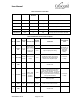
OTHER SYMPTOMS LOW OUTPUT HI INPUT HI VSWR HI TEMP CHECK FAN PA FAULT / RF DRIVE OUTPUT POWER STATUS EXCITER DRIVE PWR ON User Manual POSSIBLE CAUSE Amplifier failure. SUGGESTED ACTIONS Verify exciter signal frequency and level. Obtain RMA to have amplifier checked at factory. ON OFF ON OFF Full power No power High ON High High power input signal level has been detected. Turn off input drive. Fuse failure Disconnect AC cord. Verify exciter signal level.
ON ON No power High ON OTHER SYMPTOMS LOW OUTPUT HI INPUT HI VSWR HI TEMP CHECK FAN PA FAULT / RF DRIVE OUTPUT POWER STATUS EXCITER DRIVE PWR ON User Manual One or more inactive fans POSSIBLE CAUSE Fan failure SUGGESTED ACTIONS Turn off input drive. Allow amplifier to cool. Disconnect AC cord. Try removing any obstacles from fan blades if present. Obtain RMA to have amplifier checked at factory. ON ON ON 4.
User Manual 5 MAINTENANCE 5.1 INTRODUCTION This section contains periodic maintenance requirements for reliable amplifier operation. 5.2 PERIODIC MAINTENANCE Periodic maintenance requirements are listed in Table 5-1. Table 5-1 also lists the intervals at which the tasks should be performed. Table 5-1 Periodic Maintenance TASK INTERVAL ACTION Clean Air Vents/Check Fan 30 Days Inspect and clean per paragraph 5-3. Verify fans are working properly.
User Manual 6 RF ENERGY EXPOSURE 6.1 RF ENERGY EXPOSURE AWARENESS, CONTROL INFORMATION, AND OPERATIONAL INSTRUCTIONS FOR COMPLIANCE WITH FCC RF EXPOSURE LIMITS NOTE: This power amplifier product is intended for use in environments in which personnel have full knowledge of their exposure and can exercise control over their exposure to meet FCC limits.
User Manual a. The antenna should be mounted outside the site building on a roof, tower, or other support structure such that its location is inaccessible to personnel within the Minimum Permissible Exposure radius (see below). b. The licensee must undertake the responsibility to manage the site in accordance with the applicable regulatory requirements.
User Manual 4. In instances where the effective antenna gain (antenna gain – feedline loss) differs from the example above, the MPE radius must be calculated by the licensee. Table 4-1 presents the results of calculations of the MPE radius for a 250 Watt 406 MHz transmitter having various effective antenna gain values. Table 6-1 Calculations of the MPE Radius for a 250 Watt 406 MHz Transmitter Effective Antenna Gain Minimum Safe Distance Minimum Safe Distance (dBi) (meters) (feet) 3.0 3.83 12.6 4.
User Manual 040003A010 Rev A Page 25 of 25