
Installation and Operating Manual

User Manual
040003A010 Rev A Page 10 of 25
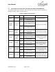
Table 3-4 Alarm Truth Table
Alarm
LED Color
Amplifier
Shutdown
PA Fault
Recovery
CHECK FAN
Red
No
High
Clean fans, replace if defective
HI TEMP
Red
Yes
High
Reduce PA temperature below 65°C
HI VSWR
Red
Yes
High
Input Re-Key
HI INPUT
Yellow
No
High
Input Re-Key
LOW OUTPUT
Yellow
No
High
Set input drive above minimum threshold
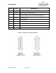
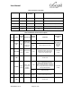
Table 3-5 Monitor Connector Description
PIN NO
NAME
SIGNAL
TYPE
DESCRIPTION
SIGNAL
STATES
CONDITION
APPROPRIATE
LOAD
1.
POWER
CTL
Analog
Input
Output Power
Level Control
(refer to section
0 and 3.5 for
limitations)
Open
Maximum output power
Signal is pulled
up internally to
10V. Pull down
signal with
appropriate
circuitry.
0-10V
Adjusts output power setting
2.
REV PWR
Analog
Output
Reverse Power
Voltage
0-10V
Uncalibrated analog voltage that is
proportional to the reflected power
detected at the amplifier output
> 100 kOhm,
< 100pF
3.
GND
Ground return
4.
HI TEMP
Digital
Output
Alarm - High
Temperature
Amplifier
Shutdown
<0.8V
Alarm – Temperature has exceeded
maximum operation threshold. The
amplifier output is shutdown. To reset the
alarm, it is necessary for the amplifier to
cool to a temperature below the maximum
safe operation threshold
> 100 kOhm,
< 100pF
>3.3V
Normal operation
5.
RXD
Digital
Input
Received data
RS232
voltages
RS232 communication interface
6.
GND
Ground return