
Installation and Operating Manual

User Manual
040003A010 Rev A Page 11 of 25
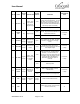
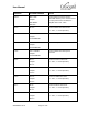
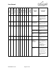
PIN NO
NAME
SIGNAL
TYPE
DESCRIPTION
SIGNAL
STATES
CONDITION
APPROPRIATE
LOAD
7
HI INPUT
Dig
Alarm – High
Input Power
Detected at
Amplifier Input
<0.8V
Alarm – RF input power exceeds
maximum power threshold level. To reset
the alarm, it is necessary to reduce RF
drive signal level and reapply RF input
power (The alarm will remain illuminated
after RF input power is removed)
>3.3V
Normal Operation
8.
CHECK
FAN
Dig
Digital Output
<0.8V
Alarm – Low fan speed or locked rotor
detected. May require fan maintenance or
replacement if defective.
> 100 kOhm,
< 100pF
>3.3V
Normal operation
9.
PA FAULT
Digital
Output
Open Collector
(External Pull-
Up Resistor
Required)
Open
Fault - CHECK FAN, HI TEMP, HI VSWR,
HI INPUT, LOW OUPUT, No Supply
Power
10.
FWD PWR
Analog
Output
Forward Power
Voltage
0-10V
Uncalibrated analog voltage that is
proportional to the forward power detected
at the amplifier output
> 100 kOhm,
< 100pF
11.
HI VSWR
Digital
Output
Alarm - High
VSWR Detected
at Amplifier
Output
<0.8V
Alarm – > 3:1 VSWR at the amplifier
output was detected. Amplifier output is
shutdown. To reset the alarm, it is
necessary to remove the high VSWR from
the amplifier output and reapply RF input
power (the alarm LED will remain
illuminated after RF input power is
removed)
> 100 kOhm,
< 100pF
>3.3V
Normal operation
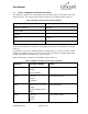
12.
EXCITER
DRIVE
Digital
Output
Minimum RF
Input Power
Indicator
<0.8V
Minimum RF power on input is present.
With no alarms amplifier is set into
transmit mode
> 100 kOhm,
< 100pF
>3.3V
RF power at input is below an activation
threshold. Amplifier is in standby mode
13.
TXD
Digital
Output
Transmitted
data
RS232
voltages
RS232 communication interface
14.
GND
Ground return (Caution: Not for external
connection, do not use)
14.