
Installation and Operating Manual

User Manual
040003A010 Rev A Page 14 of 25
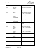
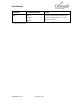
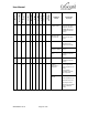
COMMAND
RETURNED ANSWER
NOTES
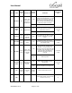
“RT?\r”
“RT=***C”
Examples:
“RT=095C”, “RT=-09C”
Return active stage temperature.
“RV?\r”
“RV=**.***V\r”
Example:
RV=47.985V
Return DC supply voltage.
“RC?\r”
“RC=**.***A\r”
Example:
“RC=09.233A\r”
Return DC supply current. Current does
not include fan current.
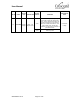
“EX=1\r”
“EX=1\r”
Enable the external control of output
power level. With the external control
enabled, the power level can be controlled
through POWER SET potentiometer and
POWER CTL analog input. The command
changes registers in the nonvolatile
memory. The external control of output
power level will remain enabled after the
amplifier is powered down. The external
control of output power level is set by
default at the factory.
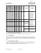
"PS=***W\r"
Example:
“PS=250W\r”
"PS=***W\r"
Example:
“PS=250W\r”
Set power level. The value range is from
050 to 250 with step 010. The controller
will round any numbers that do not meet
this criterion. The command does not
change registers in the nonvolatile
memory. If the external control of output
power level is enabled prior the command
is send, it will remain enabled after power
down.
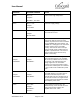
"PM=***W\r"
Example:
“PM=250W\r”
"PM=***W\r"
Example:
“PM=250W\r”
Set power level and save into the
nonvolatile memory. The value range is
from 050 to 250 with step 010. The
controller will round any numbers that do
not meet this criterion. The digital control
of output power level will remain enabled
after amplifier power down.
"PS?\r"
"PS=***W\r"
Example:
“PS=250W\r”
“PS=EX\r”
Return power level that is set in the
volatile memory. If the external control of
output power level is enabled, the
amplifier returns “EX” value.