
Installation and Operating Manual

User Manual
040003A010 Rev A Page 4 of 25
GA amplifiers cover the 406-420 MHz band without retuning. Model HA amplifiers cover the 450-
470MHz band without retuning. Amplifier specifications are shown in Table 1-1. There are seven
input ranges available as shown in Table 1-2. Closed loop power control is used to maintain a
constant output power under varying voltage, signal input level, frequency and output load
conditions. Several design features work to protect the amplifier under adverse conditions.
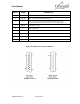
The amplifier is designed to fit into 5.25 inches (3RU) of vertical 19-inch rack space. The front
panel includes LED indicators for monitoring status and alarm conditions. This information is also
accessible via a monitor connector on the rear of the amplifier. The fan assembly draws ambient
air in from the front and blows the air across the heat sink fins out the back of the amplifier.
NOTE: The manufacturer’s rated output power of this equipment (see Table 1-1) is specified
for single carrier operation using constant-envelope modulation. This equipment is
NOT designed for multiple-carrier operation, nor is it intended to be used with non-
constant envelope modulation waveforms.
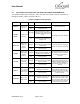
Table 1-1 Amplifier Specifications
Specification
Value
Instantaneous Bandwidth
406-420 MHz (GA models), 450-470MHz (HA models)
Output Power Range
25 W - 250 W
Input Impedance
50 Ohms
Output Impedance
50 Ohms
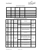
Table 1-2 Amplifier Input Power Ranges
Input Power Designator Code
Input Power Range
Nominal Gain (250W Output)
R2GA, R2HA
0.2 - 0.5 W
28.5 dB
R5GA, R5HA
0.5 - 1 W
25.0 dB
1GA. 1HA
1 - 2 W
22.0 dB
2GA, 2HA
2- 5 W
18.5 dB
5GA, 5HA
5 - 10 W
15.0 dB
10GA, 10HA
10 - 20 W
12.0 dB
20GA, 20HA
30 - 40 W
8.5 dB