
Installation and Operating Manual

User Manual
040003A010 Rev A Page 5 of 25
2 INSTALLATION
2.1 INSTALLATION INSTRUCTIONS
The amplifier is designed for installation in a rack that permits access to the rear of the unit for
connection of RF and monitor/control cables, and DC power cables or AC line cord if the unit
incorporates the internal AC power supply option. The amplifier must have a minimum of 3 inches
of open space in front and to the rear of the chassis to allow adequate air flow and ventilation. If
installed in a closed or multi-unit rack, the operating ambient temperature within the rack
environment may be greater than the room ambient. The equipment installation must be
compatible with the +60°C maximum temperature rating of the amplifier. Caution should be
exercised when rack mounting the amplifier to avoid creation of a hazardous condition due to
uneven mechanical loading. Avoid “top-heavy” or cantilever installations which may cause the
equipment rack to become unbalanced. Consideration should be given to the connection of the
equipment to the AC or DC supply circuit and the effect that overloading of the circuits might have
on overcurrent protection and supply wiring. Consideration of the appropriate current rating (10A
for 110-125VAC operation, 20A for +48VDC operation) should be used in addressing this concern.
Caution should be exercised with supply connections which are not direct connections to the
branch circuit (e.g. use of power outlet strips). Reliable grounding of rack-mounted equipment
should always be maintained.
To install the amplifier, proceed as follows:
1. Mount the amplifier in equipment rack and secure in place.
2. Connect a properly sized 50 Ohm cable and load (antenna) to the RF OUT connector on
rear of amplifier.
3. Connect the transceiver/exciter output to RF IN connector on rear of amplifier.
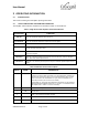
4. If monitoring of PA is desired, connect alarm cable to MONITOR connector on rear of
amplifier module. See section 3 for more details about monitor pins.
5. Connect a ground cable to the rear panel stud of the amplifier. A UL Listed ground bonding
conductor assembly is recommended, such as Harger p/n UBC61411/4KIT5,
UBC61811/4KIT5, or UBC63211/4KIT5. These ground cable interfaces consist of Harger
p/n 6-6R1 ring tongue lugs crimped to various lengths of Harger p/n 6XLPE133G/YS #6
AWG ground cable.
6. If the unit is the 48 VDC version, measure the DC output voltage of the external power
supply. DC voltage should be +48 +/- 0.5VDC. Turn off the DC voltage.
NOTE:
Make sure power supply DC is well filtered and well behaved with minimal voltage
overshoot.
Keep DC cables as short as possible (recommend no greater than 2 feet) to
minimize inductive voltage transients.
Size DC cables properly to handle the load current to minimize voltage drop during
times of transmission when current draw is highest.
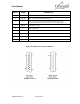
WARNING:
Turn off external primary DC power before connecting DC power cables.
Connect positive primary power wire (+48VDC) to terminal marked +48VDC and