
Installation and Operating Manual

User Manual
040003A010 Rev A Page 7 of 25
3 OPERATING INFORMATION
3.1 INTRODUCTION
This section contains general amplifier operating information
3.2 STATUS INDICATORS AND MONITOR CONNECTOR
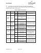
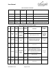
The amplifier status indicators and alarms are described in Table 3-1 and Table 3-2.
Table 3-1 High Power UHF Amplifier Status LED Indicators
STATUS LED
FUNCTION
PWR ON
Green LED. Illumination indicates unit is powered on
EXCITER DRIVE
Green LED. Illumination indicates RF input power has been applied
CHECK FAN
Red LED. Illumination indicates low fan speed or a locked rotor
HIGH TEMP
Red LED. Activates when the amplifier exceeds a safe operating temperature. Unit shuts down
until safe operating temperature returns
HIGH VSWR
Red LED. Activates when load VSWR > 3:1. Amplifier shuts down. Alarm active until RF input
removed and reapplied
HIGH INPUT
Yellow LED. Illumination indicates RF input power exceeds safe level (~125%) of rated input
power. Alarm active until RF input removed
LOW OUTPUT
Yellow LED. Can activate if power drops due to low gain or minimum specified input level is not
applied
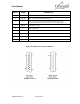
Table 3-2 Monitor Connector Description
PIN NO
NAME
DESCRIPTION
1
POWER CTL
Output Power Level Control.
POWER CTL signal is pulled up internally to 10V and pulled down by POWER SET
potentiometer located on front panel. To ensure the full adjustment range of output
power from 250W to 25W with POWER CTL signal, make sure POWER SET is
turned fully clock wise (refer to section 3.5 for details).
Both POWER CTL analog input and POWER SET potentiometer can be disabled by
digital communication interface if either “PS=***\r” or “PM=***\r” command is sent to
the amplifier (refer to Table 3-7 in section 0 for details).
2
REV PWR
Reverse Power Voltage
3
GND
Ground Return
4
HI TEMP
Alarm - High Temperature Amplifier Shutdown
5
RXD
RS232 Interface Received Data
6
GND
Ground Return