
Installation and Operating Manual

User Manual
040003A010 Rev A Page 9 of 25
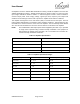
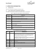
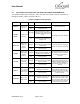
3.3 DETAILED STATUS INDICATOR AND MONITOR CONNECTOR INFORMATION
The detailed amplifier status indicators, alarm truth table and monitor connector information is
described in detail in Table 3-3 through Table 3-5.
Table 3-3 Amplifier Status Indicators
LED NAME
FUNCTION
INDICATION
CONDITION
RECOVERY
PWR ON
DC Power Up
Indicator
Green Light
Power is turned on
Power source is active
Off
Power is turned off
EXCITER
DRIVE
RF Input Power
Indicator
Green Light
RF input power is at or above
threshold. If no other alarms present,
the amplifier is placed into transmit
mode
Set RF input power above threshold
Off
RF power at input is below the
activation threshold. Amplifier is in
standby mode
CHECK FAN
Alarm - Fan
Failure or
Service
Required
Red Light
Alarm - Low fan speed or locked
rotor detected. May require cleaning
or replacement
To reset the alarm, it is necessary to
perform fan maintenance procedure
Off
Normal operation
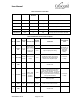
HI TEMP
Alarm - High
Temperature
Amplifier
Shutdown
Red Light
Alarm – Temperature has exceeded
maximum operation threshold. The
amplifier output is shutdown
To reset the alarm, it is necessary for
the amplifier to cool down to below
the maximum safe operation
threshold
Off
Normal operation
HI VSWR
Alarm - High
VSWR at
Amplifier Output
Red Light
Alarm > 3:1VSWR at the amplifier
output was detected. The amplifier
output is shutdown
To reset the alarm, it is necessary to
remove the high VSWR from the
amplifier output and reapply RF input
power (The alarm will remain
illuminated after RF input power is
removed)
Off
Normal operation
HI INPUT
Alarm - RF Input
Power Above
Maximum Rating
Yellow Light
Alarm - RF power at input exceeds
maximum threshold level
To reset the alarm, it is necessary to
reduce RF drive signal level and
reapply RF input power (The alarm
will remain illuminated after RF input
power is removed)
Off
Normal operation
LOW OUTPUT
Alarm - Low
Output Power
Yellow Light
Alarm – the analog control loop is
open. Amplifier is no longer able to
adjust the output power
Alarm is turned off only when the
analog control loop is closed. Check
if input signal level is within normal
limits. If RF input is within range, and
all other conditions are normal, this
indicates a potential PA failure
Off
Normal operation