
Installation and Operating Manual

User Manual
040003A009 Rev D Page 10 of 25
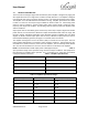
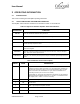
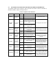
Table 3-4 Alarm Truth Table
Alarm
LED Color
Amplifier S/D
(No Output)
PA Fault
Recovery
CHECK FAN
Red
No
High
Clean fans, replace if defective
HI TEMP
Red
Yes
High
Reduce PA temperature below 65°C
HI VSWR
Red
Yes
High
Input Re-Key
HI INPUT
Yellow
No
High
Input Re-Key
LOW OUTPUT
Yellow
No
High
Set input drive above minimum threshold
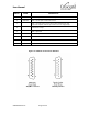
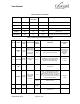
Table 3-5 Monitor Connector Description
PIN NO
NAME
SIGNAL
TYPE
DESCRIPTION
SIGNAL
STATES
CONDITION
APPROPRIATE
LOAD
1.
POWER
CTL
Analog
Input
Output Power
Level Control
(refer to section
0 and 3.5 for
limitations)
Open
Maximum output power
Signal is pulled
up internally to
10V. Pull down
signal with
appropriate
circuitry.
0-10V
Adjusts output power setting
2.
REV PWR
Analog
Output
Reverse Power
Voltage
0-10V
Uncalibrated analog voltage that is
proportional to the reflected power
detected at the amplifier output
> 100 kOhm,
< 100pF
3.
GND
Ground return
4.
HI TEMP
Digital
Output
Alarm - High
Temperature
Amplifier
Shutdown
<0.8V
Alarm – Temperature has exceeded
maximum operation threshold. The
amplifier output is shutdown. To reset the
alarm, it is necessary for the amplifier to
cool to a temperature below the maximum
safe operation threshold
> 100 kOhm,
< 100pF
>3.3V
Normal operation
5.
RXD
Digital
Input
Received data
RS232
voltages
RS232 communication interface
6.
GND
Ground return