
User's Manual


Copyright Crescend Technologies 6 Rev O
3. GENERAL OPERATING INFORMATION
3.1. INTRODUCTION
This section contains operating instructions for the amplifier.
3.2. STATUS INDICATORS
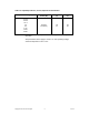
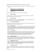
The function of the amplifier status indicators and is described in Table 3-1.
Table 3-1. Amplifier Status Indicators
STATUS LED FUNCTION
DC ON
Green LED. Illumination indicates DC Power has been applied.
LOW OUTPUT
Red LED. Activates when the output power drops to approximately
70-80% of set output power.
HIGH VSWR
Red LED. Activates when load VSWR exceeds approximately
3.5:1.
HIGH TEMP
Red LED. Activates when the amplifier exceeds a safe operating
temperature.
3.3. INITIAL STARTUP
To perform the initial start-up, proceed as follows:
Check to ensure that all input and output cables are properly connected and tightened.
Note: Use high quality coaxial cable and connectors. Properly install and solder all connectors for
reliability.
CAUTION:
Before applying power, make sure that the input and output of the
amplifier are properly terminated in 50 ohms. Do not operate the
amplifier without a load attached. Refer to Table 1-2 for input
power requirements. Excessive input power will damage the
amplifier.
NOTE:
The output coaxial cable between the amplifier and the antenna
must be 50 ohm coaxial cable.
2. Apply DC power to the amplifier. Verify that the power supply measures 13.8 ± 0.1VDC. The fan
will come on immediately for a few seconds and then turn off.
3. Visually check the indicators on each amplifier module, and verify the following:
a. The DC PWR ON indicator (green) should be on.
b. All ALARM LED indicators (red) should be off.
4. Turn on external exciter/transceiver and apply RF input signal. The fan should turn on after
approximately 3 seconds.