POWER PROCESSING AMPLIFIERS On Protect ACL Ch A Ch B Active Signal Signal Off Remote ACL CKS 800 Professional Power Amplifier On Protect ACL Ch A Ch B Active Signal Signal Off Remote ACL CKV 80 0 Professional Power Amplifier On Protect ACL Ch A Ch B Active Signal Signal Off Remote ACL CKX 500 Professional Power Amplifier OWNER’S MANUAL
Important Precautions This symbol is used to alert the operator to follow important operating procedures and precautions detailed in documentation. This symbol is used to warn operators that uninsulated “dangerous voltages” are present within the equipment enclosure that may pose a risk of electric shock. 1. Save the carton and packing material even if the equipment has arrived in good condition. Should you ever need to ship the unit, use only the original factory packing. 2.
Power Amplifier Owner’s Manual Table of Contents. Introduction . . . . . . . . . . . . . . . . . . . . . . . . . . . . . . . . . . . 2 Quick Set-Up . . . . . . . . . . . . . . . . . . . . . . . . . . . . . . . . . . 3 Unpacking . . . . . . . . . . . . . . . . . . . . . . . . . . . . . . . . . . . . 3 Installation and Mounting . . . . . . . . . . . . . . . . . . . . . . . . 3 Front Panel. . . . . . . . . . . . . . . . . . . . . . . . . . . . . . . . . . . . 3 Side Panels. . . . . . . . . . . . . . . . . . .
Introduction. Congratulations on your purchase of a Crest Audio CK family of Power Processing amplifiers. Please read this manual carefully (especially the the “Important Precautions” section located inside the front cover) as it contains information vital to the safe operation of the amplifier. Also, please fill out and return the enclosed product registration card.
Unpacking. Front Panel. Upon unpacking, inspect the amplifier. If you find any damage, notify your supplier immediately. Only the consignee may institute a claim with the carrier for damage incurred during shipping. Be sure to save the carton and all packing materials. Should you ever need to ship the unit back to Crest Audio, one of its offices, service centers, or the supplier, use only the original factory packing. If the shipping carton is unavailable, contact Crest to obtain a replacement. 1.
Rear Panel. Module Bays & Modules. The rear panel of CK Power Processing amplifiers provides three bays (Input, Network and Output/Power) configured to accept interchangeable plug-in modules. Your amplifier may have been factoryconfigured with some of the optional modules. In this case, info on the relevant modules will be enclosed in the amplifier box, or in a separate binder.
PowerSave. All CK Power Processing amplifiers come standard with PowerSave circuitry. This effectively reduces current draw and thermal emissions to a minimum when the amplifier is at idle. PowerSave operates by cutting off the bias current to the output stage after signal absence is sensed at the input. Once signal is present, PowerSave instantly restores the bias current after the first positive-going waveform.
Input Bay. Input Module Connections and Controls. Input barrier strips have a 0.325" (8.3mm) center and 0.270" (6.9mm) lug space. For connecting to the input barrier strips, a wire gauge between 14 AWG (2.5mm2) & 24 AWG (0.25mm2), and spade lugs (Panduit Part No. PNF 18-6LF-C or equivalent) are recommended. Input Module Connections and Controls Diagram.
Network Bay. Network Module Controls/Connections. CK Power Processing amplifiers come standard with a blanking panel fixed over the Network bay. When a Network module is installed in this bay, network connection is made via a pair of threepin connectors. They are wired in parallel, and form a loop-through connection. (Mates for these connectors are shipped with the Network module.) Network bus addressing is accomplished through use of the Hi and Lo Address dials.
IMPORTANT: THE POWER/OUTPUT MODULE IS NOT REMOVABLE. DO NOT ATTEMPT TO REPLACE OR REMOVE A POWER/OUTPUT MODULE ! Input Module Replacement Diagram - NC-IPN. Designed & manufactured in the USA by: Crest Audio Inc. 100 Eisenhower Dr. Paramus, New Jersey 07652 USA WIRING E USED ut Model Name Output Power @70.7V Model Name Output Power @8Ω/Ch.
TourClass® Protection Features. Every model in the CK Power Processing incorporates TourClass protection features. Derived from Crest’s extensive experience with the world’s largest sound rental companies, the TourClass group of circuits sets new standards in load and amplifier protection. ACL (Active Clip Limiting). At the amplifier’s full power, or clipping point, ACL will be activated. This is indicated by illumination of the Clip/ACL LED.
Sequential Turn-On/Turn-Off. CK Power Processing amplifiers come standard with the CC-STL Sequential Turn-On/Turn-Off (STO) Output/Power module installed. If the amplifier front power switch is set to “remote” and a voltage of between +8 to +18 VDC is applied across the “Com” and “+8 to +18V” terminals, a closure between the “In” and “Com” terminals will turn the amplifier on.
Appendices
Appendix A - CKS Series Specifications. CKS100 CKS200 CKS400 CKS800 CKS800-2 CKS1200-2 8Ω Stereo Power, 20Hz-20kHz, 0.1% THD+N 50 Watts 100 Watts 200 Watts 400 Watts 400 Watts 600 Watts 700 Watts 8Ω Stereo Power, 1kHz, 0.01% THD+N 60 Watts 120 Watts 255 Watts 440 Watts 420 Watts* 620 Watts* 715 Watts* 4Ω Stereo Power, 20Hz-20kHz, 0.1% THD+N 75 Watts 150 Watts 300 Watts 600 Watts 600 Watts 900 Watts 1100 Watts 4Ω Stereo Power, 1kHz, 0.
Appendix B - CKV Series Specifications. Output Power, 70.7 Volt CKV100 CKV200 CKV400 50 Watts 100 Watts 200 Watts CKV800 400 Watts 1200 Watts 130V Peak Output Voltage (each channel) 10Hz –20kHz, -3dB @ 148kHz Frequency Response (+0 / -0.3dB, 1W/70.7V) 10Hz –20kHz, +0/-0.2dB Power Bandwidth (full power, 1% THD+N) TourClass® Protection ACL, IGM, AutoRamp, short circuit, DC voltage, turn-on/off transient, current inrush, and sub/ultrasonic input. <0.
Appendix C - CKX Series Specifications. CKX150 CKX300 75 Watts 150 Watts CKX500 CKX800 250 Watts 400 Watts Output Power, 100 volt (50 or 70.7 volt option) 40Hz–20kHz, 0.
Appendix D - Wire Gauge Charts Stranded Cable Lgth. (ft.) Wire Gauge (AWG) Power Loss (8 ohm load) Power Loss (4 ohm load) Power Loss (2 ohm load) 5 18 16 14 12 10 0.81% 0.51 0.32 0.20 0.128 1.61% 1.02 0.64 0.40 0.25 3.2% 2.0 1.28 0.80 0.51 10 18 16 14 12 10 1.61% 1.02 0.64 0.40 0.25 3.2% 2.0 1.28 0.80 0.51 6.2% 4.0 2.5 1.60 1.01 40 18 16 14 12 10 8 6.2% 4.0 2.5 1.60 1.01 0.60 11.9% 7.7 5.0 3.2 2.0 1.20 22% 14.6 9.6 6.2 4.0 2.4 18 16 14 12 10 8 11.9% 7.7 5.0 3.2 2.0 1.20 22% 14.6 9.
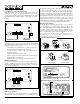
Appendix E - Distributed / Constant Voltage Systems. A distributed or constant voltage system, as shown in the figure below, uses loudspeaker step-down transformers for each speaker. The transformers are designed to deliver a specific power level into a specific load impedance when a specific voltage (the example here uses 70.7 volts) appears at the primary. A speaker transformer usually has taps on its primary, secondary, or both, so it can be used for several different power levels or speaker impedances.
Crest Audio CK Power Processing Amplifiers
Crest Audio Inc. 100 Eisenhower Dr., Paramus NJ 07652 USA TEL: 201.909.8700 FAX: 201.909.8744 http://www.crestaudio.com Printed in USA Power is serious business. v. 1.9 11/26/97 © 1997 Crest Audio, Inc.