
Owner`s manual


4
5 6 7 8
1
2 3
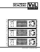
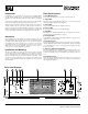
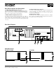
Front Panel Diagram
5.25"
133mm
19" / 483mm
2.25"
57mm
Introduction
Congratulations on your purchase of a Crest Audio power amplifier. Please
read this manual carefully (and the accompanying “Important Precautions”
pamphlet) as it contains information vital to the safe operation of your amplifi-
er.
Your VsL Series amplifier represents a major step forward in power amplifier
technology and design. It is feature-packed and engineered for value.
All VsL Series models include advanced circuitry capable of providing out-
standing reliability and sonic performance, while protection circuitry safe-
guards your speakers and the amp itself. Built to Crest Audio’s exacting stan-
dards from high quality components, VsL Series amplifiers are ideally suited
to the most punishing sound reinforcement applications - fixed or mobile.
Unpacking
Upon unpacking, inspect the amplifier. If you find any damage, notify your
dealer immediately. Only the consignee may institute a claim with the carrier
for damage incurred during shipping. Be sure to save the carton and all pack-
ing materials for the carrier’s inspection. It is a good idea to save the carton
and packing material even if the amplifier has arrived in good condition.
Should you ever need to ship the unit back to Crest Audio, one of its offices, or
service centers, use only the original factory packing.
Installation and Mounting
All VsL Series amplifiers are 3-rack space units that can mount in a standard
19-inch rack. Four front panel mounting holes are provided. Rear mounting
ears give additional support, especially important in mobile sound systems.
Because of the cables and connectors on the rear panel, a right-angle or offset
screwdriver or hex key will make it easier to fasten the rear mounting ears to
the rails. Optional rack-mount handles are available from your Crest Audio
authorized dealer.
Front Panel Controls
1. Rack Mounting Ears.
Two front panel mounting holes are provided on each mounting ear.
2. Signal LED.
Each channel has a signal LED. This LED comes on when the input signal
entering the amplifier channel is being amplified.
3. Active LED.
The green Active LED indicates the amplifier is turned on.
4. Protect LED.
If either channel is in Protect mode, this LED will light.
5. Clip LEDs.
Each channel has a clip LED. This LED comes on at clipping point, and indi-
cates that ACL (Active Clip Limiting) is engaged.
6. Fan Intake Grill.
A 110 CFM fan mounted behind the fan intake grill draws cooling air into the
amplifier. Do not block this intake!
7. Input Attenuators.
Two front-panel input attenuators adjust level for their respective amplifier
channels. Minimum attenuation (0dB) equals maximum output. In the bridged
mode, both attenuators are used to control signal level; in addition, both must
be at the same setting
8. AC Power Switch/Circuit Breaker.
VsL Series amplifiers have a combination AC switch/circuit breaker on the
front panel. If the switch shuts off during normal use, push it back to the “ON”
position once. If it will not stay on, the amplifier needs servicing. No fuses are
used.
9. Fan Exhaust Ports.
Heated air exits the amplifier through the fan exhaust ports, located on the
sides of the amplifier chassis. Be sure not to block these ports, especially when
rack-mounting the amplifier.
Page 2 VsL Series Power Amplifiers
Models VsL460, VsL900, VsL1500