
User's Manual


Multimedia Presentation System 250 Crestron MPS-250
Connectors, Controls, & Indicators (Continued)
# CONNECTORS
1
,
CONTROLS &
INDICATORS
DESCRIPTION
27
COM A & B
(2) DB9 male, bidirectional RS-232 ports;
Up to 115.2k baud, hardware and software
handshaking support for communication with
serial devices. Can also be used for modem
communications. The following table lists the
pin assignments of the serial ports.
PIN DIRECTION DESCRIPTION
1 To
MPS-250
(DCD) Data Carrier
Detect
2 To
MPS-250
(RXD) Receive Data
3 From
MPS-250
(TXD) Transmit Data
4 From
MPS-250
(DTR) Data Terminal
Ready
5 Common (GND) Ground
6 To
MPS-250
(DSR) Data Set
Ready
7 From
MPS-250
(RTS) Request To
Send
8 To
MPS-250
(CTS) Clear To Send
9 To
MPS-250
(RI) Ring Indicator
28
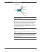
LAN
(1) 8-wire RJ-45 with two LED indicators;
10/100BaseT Ethernet port;
Green LED indicates link status;
Yellow LED indicates Ethernet activity
(Continued on following page)
18 • Multimedia Presentation System 250: MPS-250 Operations Guide – DOC. 6647A