CRESTRON Contents Series 3200 Touchpanels 1 Description................................................................................................................................. 1 Functional Description ................................................................................................ 1 Physical Description.................................................................................................... 3 Configuration Differences ...................................................
CRESTRON Series 3200 Touchpanels Description Functional Description The Series 3200 touchpanels are 10.4 inch (26.4 cm) passive matrix touchscreen control panels for the Cresnet remote control system (herein referred to as the Cresnet system). There are two Series 3200 configurations available: either lecternmount or adjustable tiltcase models. Configuration selection is based on application requirements. Refer to “Configuration Differences” on page 5 for a more detailed description of each.
CRESTRON Have a comment about Crestron’s software? Direct software related suggestions and/or complaints to Crestron via email (software@crestron.com). Do not forward any queries to this address. Instead refer to “Further Inquiries” on page 20 for assistance. Software VisionTools™ Pro (VT Pro), a design and programming Windows-based software, permits the creation of unlimited control screen variations incorporating two and three-dimensional graphics and text.
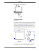
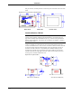
CRESTRON Hand Position for Tilting Touchpanel to Horizontal Physical Description Touchpanels The 10.4-inch (26.4 cm) touch sensitive viewing screen is located on the front of the Series 3200 touchpanel. The electronic hardware is housed in a high impact, black molded plastic enclosure for the adjustable tiltcase configurations, shown after this paragraph. This touchpanel is designed to be placed on a counter. It possesses a hinged base, which can tilt from 0 to 70 degrees.
CRESTRON four-pin network, and nine-pin RS-232 connector ports are located on the rear of the panel. Physical Views of Lectern Series 3200 Touchpanel BACK VIEW SIDE VIEW FRONT VIEW Interface Module: CN-RJ11 NOTE: The tiltcase Series 3200 touchpanel is supplied with a cable assembly that connects to the CN-RJ11 (supplied). Pinout information is provided on the next page. If the assembly must be modified in any way, Crestron cannot guarantee the behavior of the touchpanel.
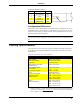
CRESTRON Six-Pin Jack Pinout (for CN-RJ11) PIN # SIGNAL COLOR 1 +24 V (Network) WHT 2 +24 V (Network) BLK 3 Y (Data) RED 4 Z (Data) GRN 5 GND (Network) YEL 6 GND (Network) BLU #1 TAB (VISIBLE, ON TOP) Configuration Differences There are two Series 3200 configurations available and selection depends on type of installation (tiltcase or lectern mount). Tiltcase panels are referred to as the CT-3200 and lectern-mount panels are called CT-3200L.
CRESTRON Leading Specifications for Series 3200 Touchpanels (Continued) SPECIFICATION DETAILS CT-3200L Lectern-Mount Model Height: 8.75 in (22.23 cm) Dimensions & Weight Width: 12.25 in (31.12 cm) Depth: 1.74 in (4.42 cm) Weight: 3.90 lb (1.77 kg) Visible View Screen Dimensions Height: 6.25 in (15.88 cm) Width: 8.25 in (20.
CRESTRON Installation Network Wiring When calculating the wire gauge for a particular network run, the length of the run and the power factor of each network unit to be connected must be taken into consideration. If network units are to be daisy-chained on the run, the power factor of each network unit to be daisy-chained must be added together to determine the power factor of the entire chain.
CRESTRON Recommended Network Cable, Liberty Wire Reference: Cresnet After completing the connections detailed in the following two sections, apply power to the touchpanel and observe illumination of the touch-sensitive screen. The touchpanel enters RUN MODE and displays a loaded panel page. To enter SETUP MODE and not RUN MODE, hold a finger to the touchscreen as power is applied. The user may configure the unit while in SETUP MODE. Refer to “Configuring the Touchpanel” on page 10 For details.
CRESTRON necessary, connect a VGA device, such as a video projector, to VGA OUTPUT. Refer to the diagram shown below. Typical Connection Diagram for Lectern-Mount Configuration CONNECT TO ANY VGA DEVICE (i.e., VIDEO PROJECTOR) CONNECT TO CONTROL SYSTEM Refer to the latest revision of DOC. 5411. CONNECT TO SERIAL PORT OF COMPUTER Use only for direct connection to PC to load panels without network. Preparation for Use The only preparation that may be required is to mount the touchpanel.
CRESTRON CT-3200 Mounting Detail Configuring the Touchpanel To configure the unit, it may be necessary to access a series of setup screens prior to viewing run-time screens that are loaded into the touchpanel for normal operation. The Main Menu for configuring the touchpanel appears when a finger is held to the touchscreen as power is applied. Remove your finger when the message "SETUP MODE" appears on the touchscreen.
CRESTRON message, "Touch Upper Left Corner", appears in the upper left corner. Touch the corner of the screen to initiate calibration. Another message, "Touch Lower Right Corner", appears in the lower right corner. Touch the corner of the screen to return to the Main Menu. Calibration Menu Diagnostics Menu The DIAGNOSTICS button from the Main Menu should only be used under supervision from a CRESTRON technical support representative during telephone support.
CRESTRON Brightness Screen brightness may need to be altered because of ambient light conditions or personal preference. Three brightness buttons, BRIGHTNESS LOW, BRIGHTNESS MED, and BRIGHTNESS HI, located in the bottom row of the Setup Menu may be selected to assign brightness setting. Current brightness setting is shown in light gray rather than black text. Contrast Screen contrast may need to be altered because of ambient light conditions, panel temperature, or personal preference.
CRESTRON After the timeout parameter has been set, touch the SAVE TIMEOUT button in the lower left corner of the screen to save the new settings. Touch the RETURN button, located in the lower right corner of the screen, to display the Setup Menu. Panel Tracking Panel tracking is a useful communication feature between touchpanels when more than one touchpanel exists on the network. Panel tracking is enabled when the PANEL TRACKING button, centrally located in the top row of the Setup Menu, is selected.
CRESTRON Two side-by-side buttons, RS-232 ON and RS-232 OFF, are located just above the RETURN button at the bottom of the Interface Menu. RS-232 is just for external control applications. Panel loading is always available; RS-232 does not have to be on. If the touchpanel is utilized in a system without a Cresnet system, ensure that the RS-232 ON button is selected. Additional RS-232 parameters must be set with the RS-232 Menu since alternative parameters may be required for successful transfers to a PC.
CRESTRON Sound Menu Save Setup and Run Program The Save Setup and Run Program button, located at the upper right corner of the Main Menu, saves all of the setup information to EEPROM and displays the main page that has been programmed into your system. Programming with SIMPL™ Windows NOTE: VisionTools Pro (VT Pro) is a Windows compatible software package for creating Crestron touchpanel screen designs. Refer to “Software” on page 2 for additional details regarding VT Pro.
CRESTRON containing a CNMSX-PRO which has a CNXRY-16 occupying slot 1. Assume that the CT-3200 is used to control a lighting system via relays in two rooms. Each room can have up to eight scenes of lighting. A scene is engaged by latching a relay. Only one scene can be activated in a room at a time. Block Diagram of System Incorporating a CT-3200 Room 1 uses relays A1 through A8; room 2 uses relays B1 through B8.
CRESTRON System View of the CNXRY-16 and CT-3200 in SIMPL Windows’ Configuration Manager Programming Manager Use the Programming Manager workspace (Project | Program System) in SIMPL Windows to select symbols and assign their respective signals. For this example, a CT-3200 and CNXRY-16 symbols were added automatically when the devices were added to the system in the Configuration Manager workspace.
CRESTRON Expand the Central Control Modules folder and double click on the CNXRY-16 for a detail view (alternatively CTRL+D or drag and drop into Detail View). Assign signals as shown below. Detail View of the CNXRY-16 in SIMPL Windows’ Programming Manager All logic symbols necessary for the SIMPL Windows program must be added from the Symbol Library in the Programming Manager workspace. In this example, drag and drop two Interlock symbols from the Memory folder into the Logic folder in Program View.
CRESTRON Reserved Join Numbers A reserved join number is a feature of the software that enables a designer to create a button on a touchpanel page that either calls up the Setup Menu, ramps contrast, etc. The table shown below provides a list of reserved join numbers available within the software.
CRESTRON Series 3200 Touchpanel Toubleshooting (Continued) TROUBLE Touchpanel is not responding and screen displays "Network Poll Error" message. POSSIBLE CAUSE(S) CORRECTIVE ACTION Incorrect network wiring. Touchpanel ID is not set to match the NET ID in the SIMPL program. Touch screen to remove message and verify correct wiring to all connectors. Touch screen to remove message and enter Performance Viewport (via SIMPL Windows or VT Pro) to poll the network.
CRESTRON Appendix: RS-232 Protocol Series 3200 touchpanels support panel operation via a host computer through the RS-232 port. Crestron recommends that the following serial data format is set. Suggested Serial Data Format Baud Rate: 38400 Data Bits: 8 Parity: None Stop Bits: 1 These settings may be altered via the RS-232 Menu when configuring the touchpanel, however, doing so may prevent Crestron supplied software from operating with the touchpanel.
CRESTRON example, requires about 576 bytes worth of commands to be sent, and could not be accomplished at any rate less than 2400 baud. Obviously, ramping several objects at once requires a baud rate several times as high. Indirect Text - Series 3200 touchpanels support a feature that permits the text field in any user-defined button to be altered on the fly in RUN mode. This is accomplished by substituting a text pointer for the text in the button.
CRESTRON Software License Agreement This License Agreement (“Agreement”) is a legal contract between you (either an individual or a single business entity) and Crestron Electronics, Inc. (“Crestron”) for software referenced in this guide, which includes computer software and, as applicable, associated media, printed materials, and “online” or electronic documentation (the “Software”).
CRESTRON If You are a business or organization, You agree that upon request from Crestron or its authorized agent, You will within thirty (30) days fully document and certify that use of any and all Software at the time of the request is in conformity with Your valid licenses from Crestron of its authorized agent. Without prejudice to any other rights, Crestron may terminate this Agreement immediately upon notice if you fail to comply with the terms and conditions of this Agreement.
CRESTRON Return and Warranty Policies Merchandise Returns / Repair Service 1. No merchandise may be returned for credit, exchange, or service without prior authorization from CRESTRON. To obtain warranty service for CRESTRON products, contact the factory and request an RMA (Return Merchandise Authorization) number. Enclose a note specifying the nature of the problem, name and phone number of contact person, RMA number, and return address. 2.
CRESTRON This page intentionally left blank. 26 • Series 3200 Touchpanels Operations Guide - DOC.
CRESTRON This page intentionally left blank. Operations Guide - DOC.