This document was prepared and written by the Technical Documentation department at: Crestron Electronics, Inc.
Crestron ST-TUNE Integrated AM/FM/TV Tuner Contents Integrated AM/FM/TV Tuner: ST-TUNE Description Functional Description Physical Description Leading Specifications Setup Network Wiring Preparation for Use Identity Code Firmware Upgrade Programming with SIMPL Windows Configure ST-TUNE Program ST-TUNE and STI-TUNE Symbols Basic Example Program Advanced Example Program Problem Solving Troubleshooting Further Inquiries Future Updates Future Firmware Upgrades Appendix 1: High-Gain AM Antenna Materials Requir
Crestron ST-TUNE Integrated AM/FM/TV Tuner Integrated AM/FM/TV Tuner: ST-TUNE Description Functional Description The ST-TUNE is a Crestron remote control network (herein referred to as the Cresnet system) optimized high-performance AM/FM/WX (Weather radio) and television (TV) tuner. The ST-TUNE provides professional audio that connects directly to and is accessed by a Cresnet system. The Cresnet system can store virtually unlimited radio station and TV channel presets.
Integrated AM/FM/TV Tuner Crestron ST-TUNE Physical Description The ST-TUNE, shown below, is housed in a black enclosure with silk-screened labels on the front and rear panels. On the front panel are 12 light-emitting diodes (LEDs) for indicating the status of the unit, the digital display for showing the band, radio station or TV channel being received, two control buttons, and three function selection buttons. All connections are made on the rear panel ports.
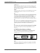
Crestron ST-TUNE Integrated AM/FM/TV Tuner ST-TUNE Ports Each ST-TUNE rear panel port has a silk-screened label. For the descriptions of the ports, refer to the following diagrams and sections. ST-TUNE Rear Panel 12VDC 1A NET NET AUDIO L VIDEO AM FM TV R CRESTRON ELECTRONICS INC. ROCKLEIGH, N.J. 07647 USA STI-TUNE (International Version) Rear Panel 12VDC 1A NET NET AUDIO L VIDEO AM FM TV R CRESTRON ELECTRONICS INC. ROCKLEIGH, N.J.
Integrated AM/FM/TV Tuner Crestron ST-TUNE AUDIO (L + R) This pair of RCA jacks output the left (white center insulator) and right (red center insulator) channel line-level audio to an audio processor such as the CNX-PAD8. The audio can also be connected to the audio inputs of a TV monitor, audio switcher and/or audio distribution equipment. VIDEO This RCA jack outputs composite TV video from the ST-TUNE.
Crestron ST-TUNE Integrated AM/FM/TV Tuner NET This LED (yellow) indicates that the SIMPL program currently loaded in the control system has a network device defined at the same NET ID code as the ST-TUNE. The LED flashes when communication with the Cresnet system and the ST-TUNE is occurring. BAND INDICATORS AND DIGITAL DISPLAY The AM, FM, WX (Weather Radio), or TV indicators contain four LEDs (red) to display the active band of the ST-TUNE.
Integrated AM/FM/TV Tuner Crestron ST-TUNE Leading Specifications The five tables in this section provide summaries of the specifications for the ST-TUNE. Dimensions and weight are rounded to the nearest hundredth unit. Leading Specifications of the ST-TUNE DETAILS 12VDC, external power pack or 9 Watts (24VDC @ 0.375A), network 3E 1 Version 1.51 or later with library update file 115 later 6 • Integrated AM/FM/TV Tuner: ST-TUNE Operations Guide - DOC.
Crestron ST-TUNE Integrated AM/FM/TV Tuner FM Tuner Specifications DETAILS Input Connector: US "F" Type Coaxial, female, 75 ohms International "IEC" Type Coaxial, 9.5mm male 87.5MHz to 107.9MHz Frequency Range 11 (dBf) Usable Sensitivity, Mono 74dB / 70dB S/N Ratio @ 65 dBf, mono / stereo 0.05% THD @ 1KHz mono/stereo Sensitivity, Adjacent / Alternate Channel 5dB / 65dB 100dB AM Rejection 55dB Stereo Separation 45dB 1VRMS Audio Output Level, Line @ 10k ohms Operations Guide - DOC.
Integrated AM/FM/TV Tuner Crestron ST-TUNE NOTE: Equipment has been tested and found to comply with the limits for a Class B digital device, pursuant to part 15 of the FCC Rules. These limits are designed to provide reasonable protection against harmful interference in a residential installation. The equipment generates, uses and can radiate radio frequency energy and, if not installed and used in accordance with the instructions, may cause harmful interference to radio communications.
Crestron ST-TUNE Integrated AM/FM/TV Tuner When calculating the wire gauge for a particular Cresnet run, the length of the run and the load factor of each network unit to be connected must be taken into consideration. If Cresnet units are to be daisy-chained on the run, the load factor of each unit to be daisy-chained must be added together to determine the load factor of the entire chain.
Integrated AM/FM/TV Tuner Crestron ST-TUNE NOTE: The location of the ST-TUNE is an important factor in the AM radio reception. The reception is also dependent on its placement and the construction of the building, locate the unit outside of any metal enclosures to achieve the best performance. A commercially available RCA extender cable (not supplied but RadioShack® part numbers 42-2352 and 274-874 are recommended), may be used to mount the antenna outside of a “shielded area or a “noisy” equipment rack.
Crestron ST-TUNE Integrated AM/FM/TV Tuner 1. Attach one of the ST-TUNEs to the control system (verify that the software is running). 2. From the SIMPL Windows or VT Pro-e menu, select Tools | Viewport to open the Crestron Viewport. 3. From the Viewport menu, select Functions | Set Network ID. The software checks the baud rate and then opens the “Set Network ID” dialog box. 4. In the “Set Network ID” dialog box, select the ST-TUNE from the Current Network Devices text window. 5.
Integrated AM/FM/TV Tuner Crestron ST-TUNE Accessing the Port Settings Dialog Box 5. Refer to the dialog box shown below and verify the communications settings. Make sure that parity is set to None, data bits to Eight, and XModem is selected. NOTE: If performing a firmware upgrade via Ethernet, select TCP/IP as the connection type and provide the IP address. Port Settings Dialog Box 12 • Integrated AM/FM/TV Tuner: ST-TUNE Operations Guide - DOC.
Crestron ST-TUNE Integrated AM/FM/TV Tuner 6. Refer to diagram below. From the Viewport menu, select Diagnostics | Report Network Devices (alternatively, depress F4). Accessing the Network Devices 7. In the Viewport return display, observe the firmware version of the ST-TUNE. 8. Perform the appropriate step. 8a. If the firmware version is version 2.17 or later, continue with this procedure. 8b. If the firmware version is prior to version 2.17, proceed to step 8 of “Appendix 3” that begins on page 28.
Integrated AM/FM/TV Tuner Crestron ST-TUNE 10. Refer to the diagram below. Select the NET ID of the ST-TUNE and then click OK. “Select Network ID” Dialog Box 11. As shown below, browse to the firmware directory, select the downloaded firmware (UPG) file and click Open. The transfer will complete automatically. Select Firmware (UPG) File NOTE: When the external power pack is disconnected from the ST-TUNE, operating power will automatically switch to Cresnet power supplied via the NET connector(s).
Crestron ST-TUNE Integrated AM/FM/TV Tuner The next four sections describe a ST-TUNE within a SIMPL Windows program. The first section provides initial configuration information, the second section details the SIMPL symbol, the third section describes how a basic example program works by using a textual description and a block diagram, and the fourth section describes the screens of an advanced example program. NOTE: The following descriptions assume that the reader has knowledge of SIMPL Windows.
Integrated AM/FM/TV Tuner Crestron ST-TUNE NOTE: All signals listed in the following tables are DIGITAL signals unless noted otherwise. A digital signal can be high (logic level of 1), low (logic level of 0), and also have rising edge (when it goes from low to high) and falling edge (from high to low) transitions. Depending upon how the symbol was created, symbol inputs may work at the logic levels or on transitions.
Crestron ST-TUNE Integrated AM/FM/TV Tuner Detail View of the STI-TUNE Symbol in SIMPL Windows’ Programming Manager Operations Guide - DOC.
Integrated AM/FM/TV Tuner Crestron ST-TUNE ST-TUNE and STI-TUNE Symbols Input Descriptions INPUT(S) FUNCTION(S) These signals perform the same functions as pressing the UP or DOWN buttons on the front panel. NOTE: The front panel buttons auto-increment after a preset period of time. These UP and DN signals engage only once on the rising edge. Therefore, in the TUNE mode, the UP signal increments the station once. This signal cycles through the AM, FM, WX, and TV bands.
Crestron ST-TUNE Integrated AM/FM/TV Tuner ST-TUNE and STI-TUNE Symbols Input Descriptions (continued) INPUT(S) WX-Station TV-Station FUNCTION(S) This analog signal is a number that sets WX frequency. Valid weather radio numbers are 16240d through 16255d. The number has an implied decimal point 2 digits from the end and must be sent in this format. For example, to go to 162.40, the analog number to be sent is 16240d. Valid WX station increments are by 1, such as 162.41, 162.42.
Integrated AM/FM/TV Tuner Crestron ST-TUNE Basic Example Program NOTE: There is no need to recreate the basic example SIMPL Windows program. The program is available from the Downloads page (EXAMPLES Library) of Crestron’s website (www.crestron.com). Search for STTUNEA.ZIP. New users are required to register in order to obtain access to the FTP site. The program provides the ability to select a band, tune a station, and engage hardcoded presets from a touchpanel.
Crestron ST-TUNE Integrated AM/FM/TV Tuner initialize symbol S-2.2 (contains the station presets). For the program logic of all functions, refer to the table below. In the block diagram, the signals labeled A are feedback to the touchpanel. Basic Example Function Symbols and Parameters Advanced Example Program NOTE: There is no need to recreate the advanced example SIMPL Windows program. The program is available from the Downloads page (EXAMPLES Library) of Crestron’s website (www.crestron.com).
Integrated AM/FM/TV Tuner Crestron ST-TUNE functions of SAP on or off and setting the TV reception mode are not applicable for the international version STI-TUNE.) The screen also shows the signal strength as a percentage. One of the features of the program is customizable presets, the name of the preset and the station can be customized at runtime. The INITIALIZE ALL PRESETS button sets all names (labels) to empty, and sets the station to 102.70 FM.
Crestron ST-TUNE Integrated AM/FM/TV Tuner ST-TUNE Troubleshooting TROUBLE Green PWR indicator LED does not illuminate. POSSIBLE CAUSE(S) CORRECTIVE ACTION VAC at wall outlet or power strip is not available. External power pack faulty. No power on network wiring. Not enough current available on network wiring. Verify VAC at wall outlet or power strip is available. Replace external power pack. Verify network wiring.
Integrated AM/FM/TV Tuner Crestron ST-TUNE Further Inquiries If after reviewing this Operations Guide, you cannot locate specific information or have questions, please take advantage of Crestron's award winning customer service team by calling: • In the US and Canada, call Crestron’s corporate headquarters at 1-888-CRESTRON [1-888-273-7876] or 1-201-767-3400. • In Europe, call Crestron International at +32-15-50-99-50. • In Asia, call Crestron Asia at +852-2341-2016.
Crestron ST-TUNE Integrated AM/FM/TV Tuner Appendix 1: High-Gain AM Antenna This appendix provides fabrication instructions of a high-gain AM antenna for use in areas of high ambience interference or weak reception. The antenna consists of a looped wire and connector. Materials Required For the list of materials required for antenna fabrication, refer to the table below. All materials are available commercially. The only tools required for antenna fabrication are a soldering iron and soldering supplies.
Integrated AM/FM/TV Tuner Crestron ST-TUNE 4. As shown below, twist the wires together at two (2) turns per inch until the length of the twisted wires is approximately 34-inches. Twist Wires Together APPROXIMATELY 34-INCHES WITH TWO TURNS PER INCH 5. If necessary, trim the ends of the wire to make them even. Strip 1/4-inch of insulation from each end of the wire. 6. Install the RCA connector cap onto the wires. 7.
Crestron ST-TUNE Integrated AM/FM/TV Tuner Appendix 2: STI-TUNE TV Receptions The table in this appendix provides a list of program numbers, channels and corresponding frequencies for TV reception of international version STI-TUNE. The information in the following table does not apply to the US version ST-TUNE. STI-TUNE TV Programs, Channels and Frequencies Operations Guide - DOC.
Integrated AM/FM/TV Tuner Crestron ST-TUNE Appendix 3: Upgrade Firmware Version Prior to 2.17 This appendix provides firmware upgrade instructions for an ST-TUNE with a firmware version prior to 2.17. To upgrade the firmware, complete the following steps. CAUTION: If the ST-TUNE contains firmware version 2.17 or later, DO NOT perform this procedure or the unit will have to be returned to Crestron. 1. Make sure that no programs accessing the COM port of the PC. 2.
Crestron ST-TUNE Integrated AM/FM/TV Tuner Port Settings Dialog Box 6. Refer to diagram below. From the Viewport menu, select Diagnostics | Report Network Devices (alternatively, depress F4). Accessing the Network Devices 7. Operations Guide - DOC. 5833A In the Viewport return display, observe the firmware version of the ST-TUNE.
Integrated AM/FM/TV Tuner Crestron ST-TUNE CAUTION: If the ST-TUNE contains firmware version 2.17 or later, DO NOT continue this procedure or the unit will have to be returned to Crestron. Perform “Firmware Upgrade” that begins on page 11. 8. Refer to diagram on the next page. From the Viewport menu, select Setup | Communications settings (alternatively, depress Alt+D) to open the Port Settings dialog box. Accessing the Port Settings Dialog Box 9. Refer to the diagram below.
Crestron ST-TUNE Integrated AM/FM/TV Tuner 10. Enter the following key sequence to (as previously defined for the product) ESC, X, R, ID, ENTER. On the front panel of the unit, the PRE, TUNE, SRCH plus either the AM, FM, WX, or TV LEDs will be illuminated. If the return ID command is executed from the Viewport, the display will show “BOOT”. 11. As shown below, select File Transfer | General File Transfer | ASCII Upload from the Viewport menu. Select ASCII Upload 12.
Integrated AM/FM/TV Tuner Crestron ST-TUNE 14. Remove operating power from the ST-TUNE, wait several seconds and reconnect power. 15. Allow at least 30 seconds after power has been reconnected then select Diagnostics | Report Network Devices in the Viewport (alternatively, depress F4). Observe Viewport return display show “ST-TUNE NEEDS FIRMWARE [1.1]” 16. Refer to diagram below.
Crestron ST-TUNE Integrated AM/FM/TV Tuner 18. As shown below, select File Transfer | Load Network Device from the Viewport menu. Select Load Network Device 19. Refer to the diagram below. Select the NET ID of the ST-TUNE and then click OK. “Select Network ID” Dialog Box 20. As shown below, browse to the firmware directory, select the downloaded firmware (UPG) file and click Open. The transfer will complete automatically. Select Firmware (UPG) File Operations Guide - DOC.
Integrated AM/FM/TV Tuner Crestron ST-TUNE NOTE: When the external power pack is disconnected from the ST-TUNE, operating power will automatically switch to Cresnet power supplied via the NET connector(s). To remove power from the unit, make sure both external power pack and NET connector(s) are removed. 21. Remove operating power from the ST-TUNE, wait several seconds and reconnect power. 22.
Crestron ST-TUNE Integrated AM/FM/TV Tuner Return and Warranty Policies Merchandise Returns / Repair Service 1. No merchandise may be returned for credit, exchange, or service without prior authorization from CRESTRON. To obtain warranty service for CRESTRON products, contact the factory and request an RMA (Return Merchandise Authorization) number. Enclose a note specifying the nature of the problem, name and phone number of contact person, RMA number, and return address. 2.
Crestron Electronics, Inc. 15 Volvo Drive Rockleigh, NJ 07647 Tel: 888.CRESTRON Fax: 201.767.7576 www.crestron.com Operations Guide - DOC. 5833A 06.01 Specifications subject to change without notice.