Crestron CHV-TSTAT & CHV-THSTAT Thermostats Operations and Installation Guide Firmware Version 1.
This document was prepared and written by the Technical Documentation department at: Crestron Electronics, Inc. 15 Volvo Drive Rockleigh, NJ 07647 1-888-CRESTRON All brand names, product names and trademarks are the property of their respective owners. ©2004 Crestron Electronics, Inc.
Crestron CHV-TSTAT and CHV-THSTAT Thermostats Contents Quick Installation Reference .....................................................................................................ii Thermostats: CHV-TSTAT and CHV-THSTAT 1 Introduction ............................................................................................................................... 1 Functions and Features ................................................................................................
Thermostats Crestron CHV-TSTAT and CHV-THSTAT Quick Installation Reference 1. Select a suitable location and run the connecting wires from the heating/cooling system and the Cresnet system. Refer to page 5 for a description of the thermostat connectors. Refer to page 7 for Network wiring details. Use the appropriate wiring diagram: • Heating or Cooling System Powered (Refer to page 9). • Separately Powered (Refer to page 10). • Three Wire Heat Only with Fan (Refer to page 11).
Crestron CHV-TSTAT and CHV-THSTAT Thermostats Thermostats: CHV-TSTAT and CHV-THSTAT Introduction Functions and Features The CHV-TSTAT and CHV-THSTAT series are wall-mounted universal thermostats that can be part of a Crestron Home® total control system. The thermostats are capable of controlling one or two-stage heating and cooling systems. Each thermostat is available in three colors: almond, black and white. The suffix ‘A’, ‘B’, and ‘W’, respectively denotes color, e.g., CHV-TSTATB is a black unit.
Thermostats Crestron CHV-TSTAT and CHV-THSTAT heat, cool, humidity or fan outputs are energized; a message indicator, so users know when a message is waiting to be read; a net indicator to denote when the network is active and a hold indicator that identifies when the thermostat is overriding the Cresnet temperature set point commands. Remote Sensors Firmware release 1.
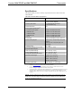
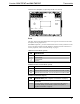
Crestron CHV-TSTAT and CHV-THSTAT Thermostats Specifications The following table provides a summary of specifications for the CHV-TSTAT and CHV-THSTAT. CHV-TSTAT and CHV-THSTAT Specifications SPECIFICATION DETAILS Power Requirements 2 Watts (24 VAC @ 83mA) Heating or Cooling System Supplied Crestron power factor <1 Watt (required for Cresnet communication only) Default Network ID Control System Update Files 2A 1,2,3 2-Series Control System Version C2-2004.CUZ or later CEN/CN-TVAV Version 5.10.
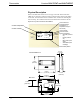
Thermostats Crestron CHV-TSTAT and CHV-THSTAT Physical Description Refer to the illustrations below and on next page. The CHV-TSTAT and CHVTHSTAT are enclosed in a plastic enclosure with four buttons and an LCD display on the front. The back of the unit has ventilation slots, and holes for mounting the unit and wiring. The ventilation slots must be unobstructed for airflow to the unit.
Crestron CHV-TSTAT and CHV-THSTAT Thermostats Connection View (Backplate, view from the front with cover removed) Z G 24V Y 24(C) 24(R) RS2 RS1 RSR RSR HUM RHU TOP W2 W/W1 B O Y2 Y/Y1 G RC RH NETWORK Ports The CHV-TSTAT and CHV-THSTAT have four types of connections on the inside back plate (refer to graphic above). NETWORK (Optional) – provides communication to the control system and Cresnet power to the CHV-TSTAT and CHV-THSTAT.
Thermostats Crestron CHV-TSTAT and CHV-THSTAT CONTROL CONNECTIONS (System Dependent) PIN DESCRIPTION HUM Energized to RHU during humidity call RHU Reference for humidifier RH Reference Heat, used for calls to heating system RC Reference Cool, used for calls to cooling system G Y/Y1 Y2 Fan, energized to RC during call for fan Compressor (stage one), energized to RC when compressor (or first stage) is run Compressor (stage two), energized to RC on two-stage systems on call for second stage O C
Crestron CHV-TSTAT and CHV-THSTAT Thermostats Setup Network Wiring NOTE: When installing network wiring, refer to the latest revision of the wiring diagram(s) appropriate for your specific system configuration, available from the Downloads | Product Manuals | Wiring Diagrams section of the Crestron website (www.crestron.com). When calculating the wire gauge for a particular Cresnet run, the length of the run and the power factor of each network unit to be connected must be taken into consideration.
Thermostats Crestron CHV-TSTAT and CHV-THSTAT System Connections Backplate - view from the front with the cover removed HUM - Energized to RHU during humidity call RHU - Reference for humidifier RSR - Remote Sensor Returns - Common sensor terminal RS1 - Remote Sensor terminal - Connect the sensor from RS1 to RSR RS2 - Remote Sensor terminal - Connect the sensor from RS2 to RSR 24(C) - 24 VAC common terminal supplies remote 24 VAC power to thermostat 24(R) - 24 VAC reference terminal.
Crestron CHV-TSTAT and CHV-THSTAT Thermostats Wiring Diagrams The wiring diagrams that follow show connections for the CHV-TSTAT and CHVTHSTAT. CAUTION: The P4 Jumper Position on the Circuit Board depends on the power method chosen, and is critical to proper operation. Improper P4 jumper position can cause equipment damage. NOTE: Ensure that the power circuits are shut off at the source before connecting the thermostat. Provide disconnect means and overload protection as required for the power supply.
Thermostats Crestron CHV-TSTAT and CHV-THSTAT Separately Powered (by an independent transformer) Backplate Connection and Circuit Board Jumper Position Transformer 24(C) 24 VAC 120 VAC 24(R) Jumper on P4 between pins 2 and 3 CRESTRON ELECTRONICS P6 P3 Z G 24V Y 24(C) 24(R) RS2 RS1 RSR RSR HUM RHU TOP NETWORK P4 P4 P4 2 3 W2 W/W1 B O Y2 Y/Y1 G RC RH 1 2 3 4 P5 P1 Backplate 1 2 3 4 Thermostat circuit board NOTE: The P4 jumper position is critical to proper operation and de
Crestron CHV-TSTAT and CHV-THSTAT Thermostats Three-Wire Heating System Connections Backplate C Integrated Control Unit Z C G 24V Y 24(C) 24(R) RS2 RS1 RSR RSR HUM RHU TOP NETWORK R W W2 W/W1 B O Y2 Y/Y1 G RC RH R W Thermostat Circuit Board CRESTRON ELECTRONICS P3 P6 1 2 3 4 P4 Jumper on P4 between pins 1 and 2 P4 1 2 P5 P1 Operations and Installation Guide – DOC.
Thermostats Crestron CHV-TSTAT and CHV-THSTAT Five-Wire Heating/Cooling System Connections Backplate C Integrated Control Unit G W W2 W/W1 R B O Y2 Y/Y1 RC G Z 24V Y NETWORK Jumper From RH to RC RH C G 24(C) 24(R) RS2 RS1 RSR RSR HUM RHU TOP Y R G Y W Thermostat Circuit Board CRESTRON ELECTRONICS P3 P6 P4 1 2 3 4 Jumper on P4 between pins 1 and 2 P4 1 2 P5 P1 12 • Thermostats: CHV-TSTAT and CHV-THSTAT Operations and Installation Guide – DOC.
Crestron CHV-TSTAT and CHV-THSTAT Thermostats Heat Pump Connections (Single & Two-Stage) Aux Heat connected to W/W1 – RH and RC jumped together Backplate C Integrated Control Unit R G W2 W/W1 B Y O Y2 Y/Y1 RC G Z NETWORK Jumper From RH to RC RH C G 24V Y 24(C) 24(R) RS2 RS1 RSR RSR HUM RHU TOP O Aux R G Y Y2 O Y2 (2nd Stage) Aux Thermostat Circuit Board CRESTRON ELECTRONICS P6 P3 P4 Jumper on P4 pins 3 & 4 1 2 3 4 P4 P5 3 4 P1 NOTE: For wiring details, refer to th
Thermostats Crestron CHV-TSTAT and CHV-THSTAT Generalized Two Stage Heat Pump Schematic Backplate Fan Relay Z G 24V Y 24(C) 24(R) RS2 RS1 RSR RSR HUM RHU TOP 1st Stage Compressor NETWORK 2nd StageCompressor W2 W/W1 B O Y2 Y/Y1 G RC RH Changeover Valve Heat Pump Transformer C 120 VAC 24 VAC R Aux Heat Transformer 120 VAC C Aux Heat Relay 24 VAC R 14 • Thermostats: CHV-TSTAT and CHV-THSTAT Operations and Installation Guide – DOC.
Crestron CHV-TSTAT and CHV-THSTAT Thermostats Installation The location of the thermostat can affect its performance and efficiency. Install the thermostat away from direct sunlight, drafts, doorways, skylights, and windows. Also make sure the thermostat is conveniently located for programming, and do not mount on an exterior wall. The thermostats may be mounted directly to drywall or to a single-gang box. Thermostats and sensors are mounted 60 inches (152.
Thermostats Crestron CHV-TSTAT and CHV-THSTAT Installation View – Single gang electrical box – horizontal mounting NOTE: Install insulation in the gang box to prevent inaccurate readings. Stud Panhead 6/32 x 1 in Single-gang electrical box (not provided) Installation view – Direct mount to wall Wall Anchors (not provided) Mounting Screws (not provided) 16 • Thermostats: CHV-TSTAT and CHV-THSTAT Backplate Operations and Installation Guide – DOC.
Crestron CHV-TSTAT and CHV-THSTAT Thermostats Thermostat Setup and Operation Setup Procedure After the thermostat is installed, it is necessary to set it up. Follow these directions. Press and hold the MODE and VIEW buttons simultaneously for five seconds to access the setup menus. The following SETUP screens appear in this order (firmware version 1.1 or lower): 1. SYSTEM 2. SYSTEM PERFORMANCE 3. HUMIDITY/FAN OPTIONS 4. DEVICE OPTIONS 5. SCREEN OPTIONS 6. DISPLAY OPTIONS 7. SENSORS 8.
Thermostats Crestron CHV-TSTAT and CHV-THSTAT 2. System Performance Press the MODE button to access the next menu, SYSTEM PERFORMANCE. Press VIEW to select preferences. Press the Arrow keys (▲▼) to select the value of the parameter.
Crestron CHV-TSTAT and CHV-THSTAT Thermostats 4. Device Options Press the MODE button to access the DEVICE OPTIONS. Press VIEW to select options. Press the Arrow keys (▲▼) to select the value of the parameter. Select Network ID VIEW SETUP: DEVICE OPTS Network ID: 2A LCD Contrast 5 T MODE Firmware Version [1.1] Bld 133 T Valid entries are 03 to FE in Hex to match the network ID set for the thermostat in SIMPL Windows Select LCD Screen Contrast (1 Lighter through 10 Darker) CRESTRON 5.
Thermostats Crestron CHV-TSTAT and CHV-THSTAT 6. Display Options Press the MODE button to access the DISPLAY OPTIONS. Press VIEW to select options. Press the Arrow keys (▲▼) to select the value of the parameter. 0 F or 0C Offset (-6 to +60) Allows the user to adjust the displayed temperature VIEW SETUP: DISP OPTIONS Temperature Units: F Temp display offset: 00 Dual Setpoint Auto: Y Main Scn Lwr Obj: HM T MODE T Use Dual Setpoint Automatic Yes or No Allows an automatic selection of setpoint range.
Crestron CHV-TSTAT and CHV-THSTAT Thermostats Select Sensor Type Temperature and/or Humidity MODE SETUP: SENSORS Sensor TEMP HUM T VIEW Internal: Remote 1: Remote 2: T USE USE USE OMIT OMIT OMIT CRESTRON Internal Sensor Temperature/Humidity in CHV-THSTAT Temperature only in CHV-TSTAT Remote Sensors CHV-RTS temperature only sensor CHV-RTHS temperature/humidity sensor Sensors may be indoor or outdoor.
Thermostats Crestron CHV-TSTAT and CHV-THSTAT Operating the Thermostat After setup, configure the thermostat using the following screens. Main Screen VIEW 66 43 o F % o 68 F HEATING HEAT ONLY ON LINE T MODE T The Main Screen displays the Current Temperature, System Mode, Fan Mode, and Set Point temperatures. The CHV-THSTAT also displays Relative Humidity and Humidifier Mode. Press the up ▲arrow button to increase the set point temperature.
Crestron CHV-TSTAT and CHV-THSTAT Thermostats 3. Humidifier (CHV-THSTAT ONLY) Humidifier Screen Pressing the MODE button displays the “Humidifier” screen. VIEW Humidifier T MODE ENABLED DISABLED T 4. CRESTRON SYSTEM Crestron System Screen VIEW Crestron Sys ONLINE HOLD T MODE Use the up ▲and down ▼arrow buttons to select ENABLED or DISABLED. T Pressing the MODE button again displays the Crestron System screen. Use the up ▲and down▼arrow buttons to select ONLINE or HOLD.
Thermostats Crestron CHV-TSTAT and CHV-THSTAT 2. OUTDOOR Outdoor Screen VIEW Outdoor T MODE 32 T o F Press the VIEW button again to display the “Outdoor” screen. This allows the user to view the outdoor temperature (if an outdoor sensor has been installed) and outdoor humidity (if available). Outdoor temperature/humidity can come from an outdoor sensor wired directly to the thermostat or through the Cresnet system from another source. This page is only displayed if enabled in the setup.
Crestron CHV-TSTAT and CHV-THSTAT Thermostats Programming Software Have a question or comment about Crestron software? Answers to frequently asked questions (FAQs) can be viewed in the Online Help section of the Crestron website (www.crestron.com). To post your own question or view questions you have submitted to Crestron’s True Blue Support, log in at http://support.crestron.com. First-time users will need to establish a user account.
Thermostats Crestron CHV-TSTAT and CHV-THSTAT 2-Series control processors. Refer to Doc. 8163C for complete descriptions and procedures concerning firmware version 2.0. Programming with Crestron D3 Pro The easiest method of programming, but does not offer as much flexibility as SIMPL Windows. Crestron D3 Pro offers automatic programming for residential and commercial systems.
Crestron CHV-TSTAT and CHV-THSTAT Thermostats C2Net-Device Slot in Configuration Manager To incorporate a CHV-THSTAT or CHV-TSTAT into the system, drag one of the symbols for the thermostat from the Crestron Sensing Modules folder of the Device Library and drop it on C2-NET Device slot in System Views. The PRO2 system tree displays the thermostat symbol in Slot 9, with a default NET ID of 2A as shown in the example graphic below.
Thermostats Crestron CHV-TSTAT and CHV-THSTAT CHV-TSTAT AND CHV-THSTAT BASIC SYMBOL The following diagram shows the basic thermostat symbols in the SIMPL Windows’ Programming Manager (firmware version 1.1 or lower only).
Crestron CHV-TSTAT and CHV-THSTAT Thermostats CHV-THSTAT AND CHV-TSTAT ADVANCED SYMBOL The advanced symbol allows additional functionality, including: Global Update and Global Page display, Function pages, and System Messaging. Refer to page 32 for a detailed description of the inputs and outputs (firmware version 1.1 or lower only). . Detail View of the Advanced CHV-THSTAT and CHV-TSTAT Symbol Digital Inputs/Outputs Operations and Installation Guide – DOC.
Thermostats Crestron CHV-TSTAT and CHV-THSTAT Detail View of the Advanced CHV-THSTAT and CHV-TSTAT Symbol Digital Outputs 30 • Thermostats: CHV-TSTAT and CHV-THSTAT Operations and Installation Guide – DOC.
Crestron CHV-TSTAT and CHV-THSTAT Thermostats Detail View of the Advanced CHV-THSTAT and CHV-TSTAT Symbol Analog Inputs/Outputs Detail View of the Advanced CHV-THSTAT and CHV-TSTAT Symbol Serial Inputs Operations and Installation Guide – DOC.
Thermostats Crestron CHV-TSTAT and CHV-THSTAT Thermostat Symbol Definitions The following tables contain a detailed description of the inputs and outputs for the basic and advanced CHV-TSTAT and CHV-THSTAT symbols (firmware version 1.1 or lower only). NOTE: For the simplest possible programming, connect an appropriate analog signal to SETPOINT_1, and possibly SETPOINT_2.
Crestron CHV-TSTAT and CHV-THSTAT Thermostats Other Digital Joins Signal Name Symbol I/O Definition GLOBAL_UPDATE_BTN Advanced Output Output that is asserted when the global update “send” button is pressed MESSAGE_ICON_ON Advanced Input Causes the front panel third text line to flash “view msg” alternately with “on line/offline,” alerting the user to check a message that was sent to the thermostat FRONT_PANEL_LOCKOUT Both Input Causes the buttons on the thermostat to become inoperable when
Thermostats Crestron CHV-TSTAT and CHV-THSTAT Humidifier Related Joins (continued) Signal Name Symbol I/O Definition OUTDOOR_HUMID_F Both Output Analog value that is output if a connected remote temperature/humidity sensor is declared as “outdoor” Can be used to distribute the reading to other thermostats for display purposes REGULATION_HUMID_F Both Output The "regulation" humidity that a thermostat is using, This is the average of the humidity sensor inputs declared "use" in set-up.
Crestron CHV-TSTAT and CHV-THSTAT Thermostats HVAC Related Analog Joins (continued) Signal Name Symbol I/O Definition REGULATION_TEMP_F Both Output Temperature used for regulation, this is the mean (averaged) temperature for all sensors declared “use”, in 10ths of degrees BUILT_IN_TEMP_F Advanced Output Temperature of the built-in sensor, in 10ths of degree, Note that the values are reported regardless of the use/OD/omit setting REM1_TEMP_F Advanced Output Temperature of remote 1 sensor, i
Thermostats Crestron CHV-TSTAT and CHV-THSTAT Setup Related Digital Joins (continued) Signal Name Symbol I/O Definition DUAL_FUEL_HP_F Advanced Output Asserted when dual-fuel heat pump system declared, In conventional heat pump systems, aux heat may be used to supplement heat pump heat. In dual-fuel setups, the aux heat output runs in place of the heat pump in cold weather. Requires outdoor temperature sensor.
Crestron CHV-TSTAT and CHV-THSTAT Thermostats Sensor Setup Related Digital Joins (continued) Signal Name Symbol I/O Definition USE_R2_HUM_F Advanced Output Asserted when using remote 2 humidity sensor OMIT_LOC_HUM_F Advanced Output Asserted when Omitting built in hum sensor (THSTAT) OMIT_R1_HUM_F Advanced Output Asserted when Omitting remote 1 humidity sensor OMIT_R2_HUM_F Advanced Output Asserted when Omitting remote 2 humidity sensor R1_H_OUTDOOR_F Advanced Output Asserted when r
Thermostats Crestron CHV-TSTAT and CHV-THSTAT Problem Solving Troubleshooting The table below provides corrective action for possible trouble situations. If further assistance is required, please contact a Crestron customer service representative.
Crestron CHV-TSTAT and CHV-THSTAT Thermostats Further Inquiries If after reviewing this Operations and Installation Guide, you cannot locate specific information or have questions, please take advantage of Crestron's award winning customer service team by calling: • In the US and Canada, call Crestron’s corporate headquarters at 1-888-CRESTRON [1-888-273-7876]. • In Europe, call Crestron International at +32-15-50-99-50. • In Asia, call Crestron Asia at +852-2341-2016.
Thermostats Crestron CHV-TSTAT and CHV-THSTAT Appendix A: Glossary Anticipators – Used to anticipate the drop or rise in temperature and energize the appropriate system before reaching the set point. Balance Point – The lowest outdoor temperature at which the refrigeration cycle of a heat pump will supply the heating requirements without the aid of a supplementary heat source. Blower (Fan) – An air-handling device for moving air in a distribution system.
Crestron CHV-TSTAT and CHV-THSTAT Thermostats Appendix B: About Heat Pumps A heat pump extracts available heat from one area and transfers it to another. Even cold air contains some heat, and heat pumps can extract heat from the outside air on a cold day and transfer it indoors to maintain a comfortable temperature. A heat pump also works in reverse during the summer, extracting heat from indoors and transferring it outdoors.
Thermostats Crestron CHV-TSTAT and CHV-THSTAT Return and Warranty Policies Merchandise Returns / Repair Service 1. No merchandise may be returned for credit, exchange, or service without prior authorization from CRESTRON. To obtain warranty service for CRESTRON products, contact the factory and request an RMA (Return Merchandise Authorization) number. Enclose a note specifying the nature of the problem, name and phone number of contact person, RMA number, and return address. 2.
Crestron CHV-TSTAT and CHV-THSTAT Thermostats This page intentionally left blank. Operations and Installation Guide – DOC.
Crestron Electronics, Inc. 15 Volvo Drive Rockleigh, NJ 07647 Tel: 888.CRESTRON Fax: 201.767.7576 www.crestron.com Operations and Installation Guide – DOC. 8163B 03.04 Specifications subject to change without notice.