Crestron CNX-PVID8x3 Video Distribution Switch Operations Guide
This document was prepared and written by the Technical Documentation department at: Crestron Electronics, Inc. 15 Volvo Drive Rockleigh, NJ 07647 1-888-CRESTRON All brand names, product names, and trademarks are the property of their respective owners. ©2005 Crestron Electronics, Inc.
Crestron CNX-PVID8x3 Professional Video Distribution Switch Contents Professional Video Distribution Switch: CNX-PVID8x3 1 Introduction ............................................................................................................................... 1 Features and Functions ................................................................................................ 1 Specifications .........................................................................................................
Crestron CNX-PVID8x3 Professional Video Distribution Switch Professional Video Distribution Switch: CNX-PVID8x3 Introduction Features and Functions The Crestron® Professional Video Distribution Switch, CNX-PVID8x3, is a CAT5 video distribution system that is capable of delivering video from a large number of separate video sources like DVD players, DSS receivers, tuners, VCRs, and cameras into a multitude of separate rooms or areas.
Professional Video Distribution Switch Crestron CNX-PVID8x3 The CNX-PVID8x3 accepts component, S-video, and NTSC/PAL composite sources, including HDTV signals, and distributes them to display devices throughout the home via standard CAT5 structured wiring. This distribution method ensures a balanced signal for long runs, allowing the user to equalize, adjust, and boost the gain of the video signal for the perfect picture for every application, in every room.
Crestron CNX-PVID8x3 Professional Video Distribution Switch hardware configuration chosen. Refer to "Hardware Configurations" on page 15 for specific connection details. CNX-PVID8x3 used without Crestron Room Solution Box In this system, the CNX-PVID8x3 has an incredible amount of flexibility with respect to making connections to all three types of video sources.
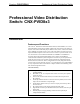
Professional Video Distribution Switch Crestron CNX-PVID8x3 Physical Description The CNX-PVID8x3 is housed in a black enclosure with labeling on the front and rear panels. LEDs on the front of the unit indicate the unit's status. All connections are made to the back of the unit. Refer to the following illustrations. CNX-PVID8x3 Front View CNX-PVID8x3 Rear View 4 • Professional Video Distribution Switch: CNX-PVID8x3 Operations Guide - DOC.
Crestron CNX-PVID8x3 Professional Video Distribution Switch CNX-PVID8x3 Physical Views Rear View 17.16 in (43.59 cm) Top View 8.45 in (21.47 cm) Front View 19.00 in (48.26 cm) PWR 5.31 in (13.49 cm) NET 5.21 in (13.24 cm) CRESTRON CNX-PVID8X3 Two mounting ears are provided for rack mounting; four square rubber feet are provided to be attached to the base of the unit for stability and to prevent slippage in tabletop mounting or stacking configurations.
Professional Video Distribution Switch Crestron CNX-PVID8x3 connect independent video sources to the CNX-PVID8x3. Each connector is supplied with RCA terminators (75 ohm). The terminators should remain attached unless the INPUT connectors of multiple units are connected (loop-through). Refer to "Signal Distribution to More than Eight Rooms" on page 21 for a description and illustration about loop-through. The last unit in the loop must have terminators installed.
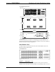
Crestron CNX-PVID8x3 Professional Video Distribution Switch CNX-PVID8x3 Indicators P R O F E S S I O N A L V I D E O D I S T R I B U T I O N S W I T C H O UT PUT PWR 1 NET 2 3 4 5 6 7 8 3 A C T IV E V I D E O 2 S E L E C T IN P U T 1 1 2 3 4 5 6 7 8 9 10 11 12 13 14 15 16 CNX-PVID8X3 CRESTRON PWR (Power) This LED illuminates when 24 volts DC from the network is supplied to the CNX-PVID8x3.
Professional Video Distribution Switch Crestron CNX-PVID8x3 Industry Compliance As of the date of manufacture, the CNX-PVID8x3 has been tested and found to comply with specifications for CE marking and standards per EMC and Radiocommunications Compliance Labelling. NOTE: This device complies with part 15 of the FCC rules.
Crestron CNX-PVID8x3 Professional Video Distribution Switch Wire Gauge Values RESISTANCE WIRE GAUGE 4 16 6 18 10 20 15 22 13 Doubled CAT5 8.7 Tripled CAT5 NOTE: All network wiring must consist of two twisted-pairs. One twisted pair is the +24V conductor and the GND conductor and the other twisted pair is the Y conductor and the Z conductor. NOTE: When daisy chaining network units, always twist the ends of the incoming wire and outgoing wire that share a pin on the network connector.
Professional Video Distribution Switch Crestron CNX-PVID8x3 set with the entire Cresnet system intact. This method requires the use of the Crestron Viewport version 3.35 or later. Use the appropriate method to set the CNX-PVID8x3 Net ID. Method A (Cresnet address-settable ID) 1. Ensure that the CNX-PVID8x3 is the only device connected to the control system. 2. Open the Crestron Viewport. 3. From the Viewport menu, select Functions | Set Network ID.
Crestron CNX-PVID8x3 Professional Video Distribution Switch “Set Net ID by TSID” Window 4. Click on the Search for Touch Settable Devices button. The system searches the network and lists all TSID-enabled devices found. The list is similar to the report produced by pressing F4 (Report Network Devices); the first eight digits of each line constitute the TSID number (hexadecimal form of the serial number). 5.
Professional Video Distribution Switch Crestron CNX-PVID8x3 “Serial Number to TSID Conversion Tool” Window 3. Enter the serial number or TSID number as instructed; press the appropriate button to obtain the corresponding number. NOTE: Enter serial numbers, including spaces, exactly as they appear on the unit label. Alpha characters in serial numbers or TSID numbers may be entered in upper or lower case.
Crestron CNX-PVID8x3 Professional Video Distribution Switch 2. Using a #2 Phillips screwdriver, remove the 16 cover screws from the top (four screws) and sides (six per side) of the CNX-PVID8x3. 3. Lift and remove the CNX-PVID8x3 top cover. 4. Use the supplied cable (15863) to connect board 1 (bottom board) to board 3 (top board), as shown in the diagram that follows this step. Location of Cable Connection (Side View of Unit) USE CABLE FOR CONNECTION OF LEVEL 1 TO LEVEL 3 ONLY 5.
Professional Video Distribution Switch Crestron CNX-PVID8x3 • The unit should be mounted at the bottom of the rack if it is the only unit in the rack. • When mounting this unit in a partially filled rack, load the rack from the bottom to the top with the heaviest component at the bottom of the rack. • If the rack is provided with stabilizing devices, install the stabilizers before mounting or servicing the units in the rack.
Crestron CNX-PVID8x3 Professional Video Distribution Switch Feet Location (Bottom View of Unit) ATTACH FEET NEAR CORNERS OF THE UNIT Hardware Hookup Refer to the hookup diagram after this paragraph. Other than making the power connection last, complete the connections in any order. NOTE: For specific details regarding input connections, refer to "Hardware Configurations" on page 15 if the CNX-PVID8x3 connects to Crestron Room Solution Boxes within the system.
Professional Video Distribution Switch Crestron CNX-PVID8x3 and 3 are connected via the cable assembly). Refer to the table after this paragraph for a tabulation of the relationship between input levels and video formats.
Crestron CNX-PVID8x3 Professional Video Distribution Switch Out-of-the-Box Configuration AKA: 16 Sources of Any Type (Video, S-Video, Component) This configuration is aptly named because the internal jumpers are intact, as shipped, and the supplied cable assembly is not used. Therefore, the unit is ready for immediate use and is capable of distributing a combination of up to 16 sources of any type. The built-in versatility of this configuration makes it the most popular and easiest to use.
Professional Video Distribution Switch Crestron CNX-PVID8x3 Cabled Configuration (Composite/S-Video Only) AKA: 16 Video & Up to 16 S-Video or Video Sources NOTE: Dealing with a system that contains more than 16 sources? This configuration may be preferred as long as the system does not contain component video. To achieve this configuration, the unit must be opened and the cable assembly attached. Refer to "Cabling and Jumpers" on page 12 for details. The internal jumpers remain intact.
Crestron CNX-PVID8x3 Professional Video Distribution Switch Illustration of Composite/S-Video Only Configuration Cabling and Jumpering Internal Boards: PHYSICAL CONNECTIONS: 1 Cable between level 1 and level 3 is in place. 2 3 4 5 6 7 INPUT 8 9 10 11 12 3 13 14 15 16 COMPOSITE SOURCES*: PHYSICALLY CONNECT TO LEVEL 3 (INPUTS 1 THROUGH 16), BUT ARE LOGICALLY AN EXTENSION OF LEVEL 1. 2 Nine jumpers remain in their original location (no jumpers on the jumper holder).
Professional Video Distribution Switch Conditions of this configuration; please read carefully! Crestron CNX-PVID8x3 This configuration allows for up to 24 sources. However, those sources cannot exceed more than eight component, more than 16 S-video (assuming no component sources), more than 24 composite (when there is no S-video and no component). The illustration after this paragraph depicts a system that utilizes the limited quantity of any-type configuration.
Crestron CNX-PVID8x3 Professional Video Distribution Switch Configuration Wiring Guidelines Once a configuration is chosen and any appropriate physical modifications to the CNX-PVID8x3 have been made, wiring can begin. Refer to the following guidelines. • Begin adding component sources at input 16 and work toward input 1 on all three levels. • Add composite sources beginning at input 1. In the out-of-box configuration, add sources on level 1. For any other configuration, begin on level 3.
Professional Video Distribution Switch Crestron CNX-PVID8x3 Video Distribution Expansion with Additional CNX-PVID8x3s VIDEO SIGNAL SOURCE CONNECTION 1 2 1 OUTPUT 2 3 NET 4 SETUP 24 Y Z G 3 5 6 7 8 1 2 3 4 1 2 5 OUTPUT 3 4 6 7 8 SETUP 24 Y 2 5 6 7 8 1 2 3 4 5 6 7 8 8 ROOMS (EITHER RCA OR CAT5 CONNECTIONS) 1 C RE ST RO N E L E C T R O N IC LOOP-THROUGH 1 2 1 OUTPUT 2 3 NET 4 Z G 3 5 6 7 8 1 2 3 4 1 2 5 OUTPUT 3 4 6 7 8 SETUP 24 Y 2 5
Crestron CNX-PVID8x3 Professional Video Distribution Switch Programming Software Have a question or comment about Crestron software? Answers to frequently asked questions (FAQs) can be viewed in the Online Help section of the Crestron website. To post a question or view questions you have submitted to Crestron’s True Blue Support, log in at http://support.crestron.com./ First-time users will need to establish a user account.
Professional Video Distribution Switch Crestron CNX-PVID8x3 Programming with SIMPL Windows NOTE: The following are acceptable file extensions for programs that include a CNX-PVID8x3, developed for specific control system types: .smw projectname.smw (source file) .spz projectname.spz (compiled file for 2-series) .bin projectname.bin (compiled file for CNX generation) .csz projectname.csz (compiled file for CNX generation with SIMPL+) .ush projectname.
Crestron CNX-PVID8x3 Professional Video Distribution Switch C2Net Device Slot in Configuration Manager To incorporate a CNX-PVID8x3 into the system, drag the CNX-PVID8x3 from the Cresnet Control Modules | Cresnet Video Modules folder of the Device Library and drop it in System Views. The PRO2 system tree displays the CNX-PVID8x3 in Slot 9, with a default Net ID of 41 as shown in the following illustration.
Professional Video Distribution Switch Crestron CNX-PVID8x3 the program. Always ensure that the hardware and software settings of the Net ID match. For Net ID hardware setting details, refer to “Identity Code” on page 9. CNX-PVID8x3 Symbols The inputs to the CNX-PVID8x3 symbol require the analog equivalent (typically 1 through 16, but could go up to 32) so that the video source physically connected to a given input can be switched to the specified output.
Crestron CNX-PVID8x3 Professional Video Distribution Switch Detail View of the CNX-PVID8x3 Symbol in SIMPL Windows' Programming Manager CNX-PVID8x3 Symbol Input Descriptions INPUT(S) Operations Guide - DOC. 8159A FUNCTION(S) Src-For-Out-1Level-1 through Src-For-Out-8Level-1 Provide the analog equivalent (1 through 16) via the Analog Initialize symbol (decimal format) on this line so that the video source connected to the given input (on level 1) can be switched to the specified output on level 1.
Professional Video Distribution Switch Crestron CNX-PVID8x3 CNX-PVID8x3 Symbol Output Descriptions OUTPUT(S) FUNCTION(S) Sense-in-1-Level-1 through Sense-in16-Level-1 High if a video signal is detected on the specific input (1 – 16) on level 1; otherwise, 0 (zero). Sense-in-1-Level-2 through Sense-in16-Level-2 High if a video signal is detected on the specific input (1 – 16) on level 2; otherwise, 0 (zero).
Crestron CNX-PVID8x3 Professional Video Distribution Switch Symbol Designation: CNX-PVID8x3J13 For this symbol designation, level 3 is connected to level 1 with the supplied cable. This is the equivalent of extending level 1 with 16 additional inputs. Detail View of the CNX-PVID8x3J13 Symbol in SIMPL Windows' Programming Manager CNX-PVID8x3J13 Symbol Input Descriptions INPUT(S) Operations Guide - DOC.
Professional Video Distribution Switch Crestron CNX-PVID8x3 CNX-PVID8x3J13 Symbol Output Descriptions OUTPUT(S) FUNCTION(S) Sense-in-1-Level-1 through Sense-in16-Level-1 High if a video signal is detected on the specific input (1 – 16) on level 1 (including extension from level 3); otherwise, 0 (zero). Sense-in-1-Level-2 through Sense-in16-Level-2 High if a video signal is detected on the specific input (1 – 16) on level 2; otherwise, 0 (zero).
Crestron CNX-PVID8x3 Professional Video Distribution Switch Symbol Designation: CNX-PVID8x3J13S For this symbol designation, level 3 is divided in half by removing jumpers. Furthermore, half of level 3 (inputs 1 through 8) is connected to level 1 with the supplied cable. This is the equivalent of extending level 1 with eight additional inputs and still allowing for connections to component video sources.
Professional Video Distribution Switch Crestron CNX-PVID8x3 CNX-PVID8x3J13S Symbol Input Descriptions (continued) INPUT(S) FUNCTION(S) Src-For-Out-1Level-2 through Src-For-Out-8Level-2 Provide the analog equivalent (1 through 16) via the Analog Initialize symbol (decimal format) on this line so that the video source connected to the given input (on level 2) can be switched to the specified output on level 2.
Crestron CNX-PVID8x3 Professional Video Distribution Switch DEPICTION OF LEVELS ON BACK OF UNIT: LEVEL 3 8 IN X 8 OUT LEVEL 2 16IN X 8OUT LEVEL 1 24IN X 8OUT DEPICTION OF SYMBOL IN SIMPL WINDOWS: VIA THE ANALOG INITIALIZE SYMBOL (DECIMAL FORMAT) ASSIGN THE ANALOG EQUIVALENT (1 - 16 FROM LEVEL 1 AND 17 - 24 FROM LEVEL 3) OF AN INPUT TO A SPECIFIC OUTPUT (1 - 8) ON LEVEL 1 VIA THE ANALOG INITIALIZE SYMBOL (DECIMAL FORMAT) ASSIGN THE ANALOG EQUIVALENT (1 - 16 FROM LEVEL 2) OF AN INPUT TO A SPECIFIC O
Professional Video Distribution Switch Crestron CNX-PVID8x3 NOTE: The Crestron Viewport utility performs multiple system tasks, primarily via an RS-232 or TCP/IP connection between the control system and a PC. It is used to observe system processes, upload new operating systems and firmware, change system and network parameters, and communicate with network device consoles and touchpanels, among many other tasks. Viewport can also function as a terminal emulator for generic file transfer.
Crestron CNX-PVID8x3 Professional Video Distribution Switch Typical Connection Diagram when Uploading 1. Open the Crestron Viewport. Either launch the stand-alone version of Viewport, or start SIMPL Windows or VT Pro-e, and from the menu bar, select Tools | Viewport. 2. Refer to the figure after this step. From the Viewport menu, select Setup | Communications settings (alternatively, press Alt+D) to open the “Port Settings” window. Setup | Communications Settings Command 3. Operations Guide - DOC.
Professional Video Distribution Switch Crestron CNX-PVID8x3 “Port Settings” Window NOTE: The parameters shown in the illustration above are the port settings for a 2-Series control system. Consult the Operations Guide for the control system being used, for exact parameter selection. 4. To verify communication, select Diagnostics | Establish Communications (Find Rack). This should display a window that gives the COM port and baud rate.
Crestron CNX-PVID8x3 Professional Video Distribution Switch File Transfer | Send Program Command 3. The “Send Program” window appears, as shown after this step. Click Browse, locate the compiled file (.spz for PRO2), and click Open. This will display the program's header information and enable one or both of the What to Send check boxes. If the program does not contain any SIMPL+ modules, only the SIMPL Program check box will be enabled.
Professional Video Distribution Switch Crestron CNX-PVID8x3 Firmware Upgrade A firmware upgrade file has the extension .upg. To take advantage of all the available features, it is important that the unit contains the latest firmware. Please check the Crestron website for the latest version of firmware. Not every product has a firmware upgrade, but as Crestron improves functions, adds new features, and extends the capabilities of its products, firmware upgrades are posted.
Crestron CNX-PVID8x3 Professional Video Distribution Switch “Open” Window 4. Browse to the desired firmware file and click Open to begin the transfer. Problem Solving Troubleshooting The following table provides corrective action for possible trouble situations. If further assistance is required, please contact a Crestron customer service representative. CNX-PVID8x3 Troubleshooting TROUBLE CNX-PVID8x3 does not function. PWR LED does not illuminate. NET LED does not illuminate.
Professional Video Distribution Switch Crestron CNX-PVID8x3 Further Inquiries If you cannot locate specific information or have questions after reviewing this guide, please take advantage of Crestron's award winning customer service team by calling the Crestron corporate headquarters at 1-888-CRESTRON [1-888-273-7876]. For assistance in your local time zone, refer to the Crestron website (http://www.crestron.com/) for a listing of Crestron worldwide offices.
Crestron CNX-PVID8x3 Professional Video Distribution Switch Return and Warranty Policies Merchandise Returns / Repair Service 1. No merchandise may be returned for credit, exchange, or service without prior authorization from CRESTRON. To obtain warranty service for CRESTRON products, contact the factory and request an RMA (Return Merchandise Authorization) number. Enclose a note specifying the nature of the problem, name and phone number of contact person, RMA number, and return address. 2.
Professional Video Distribution Switch Crestron CNX-PVID8x3 This page intentionally left blank. 42 • Professional Video Distribution Switch: CNX-PVID8x3 Operations Guide - DOC.
Crestron CNX-PVID8x3 Professional Video Distribution Switch This page intentionally left blank. Operations Guide - DOC.
Crestron Electronics, Inc. 15 Volvo Drive Rockleigh, NJ 07647 Tel: 888.CRESTRON Fax: 201.767.7576 www.crestron.com Operations Guide – DOC. 8159A 03.05 Specifications subject to change without notice.