CRESTRON GREEN LIGHT™ Power Switching Introduction CRESTRON GREEN LIGHT power switching cabinets come pre-configured with GLXP modules already installed. The cabinets only require installation and wiring of feed and load circuits. Industry Compliance The cabinet and modules are Listed to applicable UL Standards and requirements by Underwriters Laboratories Inc.
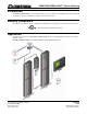
Power Switching CRESTRON GREEN LIGHT™ Physical Description This section shows the exterior and interior dimensions of the CRESTRON GREEN LIGHT cabinet.
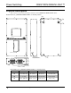
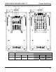
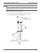
CRESTRON GREEN LIGHT™ Power Switching Interior Dimensions of CRESTRON GREEN LIGHT Cabinets (120/208 VAC, left; 277/480 VAC, right) 1 7 8" 1 7 8" (48 mm) (48 mm) 2" 2" (51 mm) (51 mm) 8 18" (207 mm) 8" (204 mm) 6 1 4" (159 mm) 3 7 8" (99 mm) H1 H1 Interior Dimensions of CRESTRON GREEN LIGHT Cabinets 120 Service 277 Service DIMENSION 12 Breaker 30 Breaker 42 Breaker 12 Breaker 30 Breaker 42 Breaker H1 8 3/4” (223 mm) 15 1/8” (385 mm) 18 1/8” (461 mm) 7 1/16” (180 mm) 12 1/16” (310 mm)
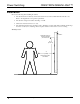
Power Switching CRESTRON GREEN LIGHT™ Installation Observe the following when installing the cabinet: • The cabinet must be mounted by a licensed electrician in accordance with all national and local codes. Refer to the diagram below for specific requirements. • The cabinet is designed for surface mounting on a wall. • Cabinets are intended for indoor use only. • The ambient temperature range should be 32°F to 104°F (0°C to 40°C). The relative humidity should range from 10% to 90% (non-condensing).
CRESTRON GREEN LIGHT™ Power Switching Wiring NOTE: All wiring must be installed in accordance with all local and national electrical codes. NOTE: Refer to the torque settings specified on pages 6, 7 and 8. CRESTRON GREEN LIGHT cabinets are shipped with GLXP modules installed and prewired to the branch circuit breakers.
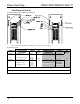
Power Switching CRESTRON GREEN LIGHT™ Feed Wiring (Section A) Feed Wiring for MLO (left) and MCB (right) Applications Refer to the following table for information on wiring the feed to the panel. Feed Wire Information TERMINAL Neutral and Main Lugs Neutral Bus 120 Volt Models CONNECTOR MAX TORQUE WIRE RANGE 10-2/0 AWG (CU) or 6-2/0 AWG (AL) 15 lb-ft (20.3 Nm) 6 - 300 kcmil (CU or AL) 21 lb-ft (28.5 Nm) 20 lb-in (2.3 Nm) 25 lb-in (2.8 Nm) 35 lb-in (4.
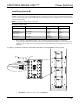
CRESTRON GREEN LIGHT™ Power Switching Load Wiring (Section B) CAUTION: Bypass jumpers are provided on each output to allow testing and to protect the module during installation. The jumper shorts the L and SW terminals so that the load circuit is energized when the branch breaker is on. Do not remove the bypass jumper until all feed and load wiring has been completed, and the circuits have been tested for electrical faults. NOTE: Use copper conductors only – rated 75°C.
Power Switching CRESTRON GREEN LIGHT™ The GLXP-DIMFLV8 also requires wiring the terminals for 0-10 VDC control wire. Refer to the following diagram when connecting the dimmable ballast. Each control wire terminal accepts one 12 – 28 AWG wire. 0-10 VDC Control Wiring for GLXP-DIMFLV8 Only TO + ON 4-WIRE LOADS (PURPLE) TO - ON 4-WIRE LOADS (GRAY) 2.
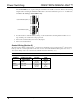
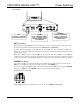
CRESTRON GREEN LIGHT™ Power Switching BLUE BLACK RED WHITE Connector Wiring NET: TO CONTROL SYSTEM AND OTHER CRESNET DEVICES POWER: 24 VDC JUMPERED FROM NET PORT or EXTERNAL SUPPLY.
Power Switching CRESTRON GREEN LIGHT™ To power the modules externally from a Cresnet 24 VDC power supply, connect the external power supply to the EXT and G pins on the POWER supplied connector as shown in the following diagram. Providing Cresnet Power Externally CRESTRON 24 VDC POWER SUPPLY G 24 When properly connected and receiving 24 VDC power externally, the green LED next to the MODULES port will light.
CRESTRON GREEN LIGHT™ Power Switching Testing Manual Control A lighting module can be manually controlled from its front panel. GLXP-SW and GLXP-HSW Modules: The state of each output can be manually controlled from the front panel. To toggle the output between off and on, tap the appropriate ON/OFF button. The corresponding LED illuminates and the output state is shown on the NET ID display (“oF” for off, “On” for on) for two seconds after the button is released.
Power Switching CRESTRON GREEN LIGHT™ System Operation and Commissioning This cabinet has been designed as a component of a programmed Crestron system. System commissioning by an authorized Crestron representative must be performed to ensure system operation. Once the cabinet has been wired and the modules have been tested, contact Crestron at 1-888-CRESTRON [1-888-273-7876] to schedule commissioning. 12 • CRESTRON GREEN LIGHT Power Switching Installation Guide – DOC.
CRESTRON GREEN LIGHT™ Power Switching Problem Solving Troubleshooting The following table provides corrective action for possible trouble situations. If further assistance is required, please contact a Crestron customer service representative. Troubleshooting TROUBLE POSSIBLE CAUSE(S) CORRECTIVE ACTION Module(s) does not function. Power not delivered to the module.
Power Switching CRESTRON GREEN LIGHT™ Appendix A: Setting Module Net IDs The following procedure will normally be performed by an authorized Crestron representative as part of the System Commissioning phase. For system wiring and basic testing as described on pages 5 and 11, it is not necessary to perform this step.
CRESTRON GREEN LIGHT™ Power Switching Appendix B: Module Specifications Specifications for the GLXP modules are listed in the following table.
Power Switching CRESTRON GREEN LIGHT™ Return and Warranty Policies Merchandise Returns / Repair Service 1. No merchandise may be returned for credit, exchange or service without prior authorization from CRESTRON. To obtain warranty service for CRESTRON products, contact an authorized CRESTRON dealer. Only authorized CRESTRON dealers may contact the factory and request an RMA (Return Merchandise Authorization) number.