This document was prepared and written by the Technical Documentation department at: Crestron Electronics, Inc.
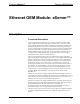
Crestron eServer™ Ethernet OEM Module Demo Already Installed! The eServer™ comes with a demonstration already factory loaded. The demo consists of a few web pages created with VisionTools™ Pro-e and a SIMPL+ module. The purpose of the demo is to prove the easy use of the eServer. Crestron is only exercising one of the many features of the eServer by using this preloaded demo to tell the eServer story. Refer to the "Quick Start" below for immediate demo access.
Ethernet OEM Module Crestron eServer™ Contents Demo Already Installed!.............................................................................................................i Quick Start..................................................................................................................................i Ethernet OEM Module: eServer™ 1 Description.................................................................................................................................
Crestron eServer™ Ethernet OEM Module Ethernet OEM Module: eServer™ Description Functional Description Crestron expands Internet technology by providing a compact, powerful control engine combined with a built-in web server. The eServer™ is a one port control system capable of making any serially controlled device an Internet appliance with minimal development work. The eServer brings Ethernet technology to industry peers in a plug-and-play format.
Ethernet OEM Module Crestron eServer™ • Baud rates may be one of the following possible rates: 300, 1200, 1800, 2400, 3600, 4800, 7200, 9600, 14400, 19200, 28800, 38400, 57600, and 115200. • Parity may be even, odd, none, or zero stick (parity bit always 0). When specifying the parity use E, O, N, or Z, respectively. • Data bits may be 7 or 8. • Stop bits may be 1 or 2. • Both XON/XOFF handshaking and RTS/CTS handshaking are supported.
Crestron eServer™ Ethernet OEM Module eServer Ports There are two ports on each of the two shorter side panels of the eServer. Each port has a silk-screened label located on the top panel. Refer to the illustration and descriptions below. eServer Ports 12V DC .5A DEVICE COM IN ETHERNET 12VDC .5A This DC power socket connector is used to supply power via an external AC power pack. Crestron recommends and supplies specific power packs for its network devices.
Ethernet OEM Module Crestron eServer™ COM IN This 9-pin connector (DB9F) is used as a pass-through for device control. This bidirectional serial port is used for RS-232 communication. It can also be used for configuring the device with IP address, mask, etc. NOTE: This port is also known as the Console (Main) port in some setup menus discussed in "port" on page 15. NOTE: The pinout of each 9-pin port is non-standard (refer to table after this note).
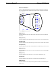
Crestron eServer™ Ethernet OEM Module eServer Indicators There are eight LED indicators located on the top panel of the eServer. Each has a silk-screened label. Refer to the illustration below and the descriptions that follow. eServer Indicators DEVICE ETHERNET ETHERNET DEVICE PWR (Power) This LED illuminates when 12 volts (from the external power pack) is supplied to the eServer. RXD (Ethernet) This LED illuminates when the Ethernet port on the eServer receives Ethernet data.
Ethernet OEM Module Crestron eServer™ Leading Specifications The table below provides a summary of leading specifications for the eServer. Dimensions and weight are rounded to the nearest hundredth unit. Leading Specifications of the eServer SPECIFICATION DETAILS Power Requirements 12 VDC, 500 mA (domestic) SIMPLTM Windows® Version 1.40.04 or later1 with library update file smwlib62.exe & update document smwlib62.txt or later Version 2.1.
Crestron eServer™ Ethernet OEM Module Crestron Control Crestron control is defined as an interface to a Crestron Ethernet device. Implementation of this method is necessary for a device to communicate with a Crestron control system. Use of this interface method does not place design limitations on the project. For example, a device can implement a Crestron control system interface, have a web interface, and have a custom PC application communicating to the same eServer. Refer to configuration # "2.
Ethernet OEM Module Crestron eServer™ control assuming Crestron software tools such as VT Pro-e or the e-control SDK were used to design the pages and the pages were uploaded to the eServer. Refer to "Appendix B: Uploading Web Pages" on page 33 for uploading details. Not only is control available, but almost any other type of web document may be linked to the device page. Links can include any of the following.
Crestron eServer™ Ethernet OEM Module Crestron Control System Control of a Device Crestron Control System Control Ethernet SIMPL+ LOGIC ENGINE RS-232 DEVICE eServer Once the SIMPL+ module is created, it can be uploaded to the device via the serial or Ethernet port using the Crestron Viewport. Refer to "Appendix C: Uploading a SIMPL+ Program" on page 35 for details regarding the loading of a program from Viewport.
Ethernet OEM Module Crestron eServer™ Web Browser Control of a Device Utilizing PC-based Web Server and Crestron CNX Gateway Software PC Web Pages Stored Files for Web Server Web Browser Control CNX Gateway Control Ethernet SIMPL+ LOGIC ENGINE RS-232 DEVICE eServer Another rationale for this configuration is if a device expects to utilize many connections (more than five). The CNX gateway allows many more than five simultaneous connections.
Crestron eServer™ Ethernet OEM Module 5. Custom Application Control of a Device Through the eServer Utilizing Standard TCP/IP Sockets This configuration is only for advanced designers. To implement a custom application using this configuration, a designer must understand the low-level details of how to program standard TCP/IP sockets. This communication path passes all data through to the serial port (bypassing the SIMPL+ module).
Ethernet OEM Module Crestron eServer™ device, a unique IP address, subnet mask, default router, and IP table settings must be defined. These settings among others can be defined using setup menus. A future release of the Crestron Viewport will provide integrated tool support. The eServer setup menus can be accessed only after connecting the communications port of the PC to the COM IN port on the eServer. A serial cable is provided in the dealer kit.
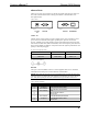
Crestron eServer™ Ethernet OEM Module Activity in the Viewport Window Enter a question mark (?) and depress ENTER to display the Main Menu, shown after this paragraph. NOTE: Use the default font for the return message to appear correctly. The Viewport default font is Terminal Regular 9. Main Menu in Viewport Window Commands are listed in the left-most column with a brief description in the rightmost column. Notice that DOS-type commands are prevalent (e.g., dir *.jpg). Operations Guide - DOC.
Ethernet OEM Module Crestron eServer™ Descriptions prefixed with [?] indicate that help is available for that command and can be displayed by entering the command, a space, and question mark (?). The following subsections provide a brief description of some commands. Command entry is not case sensitive. The user only needs to enter the characters of a command that make it unique from another (i.e., for the Add_master command, the user only needs to enter “add_m”).
Crestron eServer™ Ethernet OEM Module ip_adr Enter the “ip_adr” command and depress ENTER to display the IP address of the connected eServer. To change the IP address, enter the new IP address after the “ip_adr” command. For example to change the IP address of the connected eServer to 132.149.2.122, enter the following: ip_adr 132.149.2.
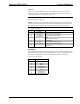
Ethernet OEM Module Crestron eServer™ Sample Response to the “port” Command As noted in the description column in the Main Menu, a typical port command has the following format: port device[,baud][,N81][,option ON:OFF] The command is not case sensitive. Parts of the command enclosed by brackets ([ ]) are optional and need not be entered unless a change is necessary. There are several port options that can satisfy the [option] [ON:OFF] part of the command.
Crestron eServer™ Ethernet OEM Module baud: • Use any valid baud rate (300,1200, 1800, 2400, 3600, 4800, 7200, 9600, 14400, 19200, 28800, 38400, 57600, and 115200). Defaults to 9600 if baud is not specified. comspecs (which includes parity, data, and stop bits): • Use any valid comspec variation (i.e., N81, E72, O71, etc). Defaults to N81 if comspecs are not specified.
Ethernet OEM Module Crestron eServer™ 1 Type system and depress ENTER. 2 Viewport responds with “Start XMODEM xmit now” on one line and proceeds to display one “C” after another. 3 While the Cs are appearing, select General File Transfer | XModem1K Upload from the File Transfer command. 4 From the “Open” window, browse and highlight the upload file. Click on OK. 5 The “Transfer In Progress” window appears while the transfer is in progress.
Crestron eServer™ Ethernet OEM Module cancel Use the “cancel” command to terminate an operating system upgrade that is in progress. This command can be used at any time (e.g., after a "prepare" comand or while a transfer file is in progress. version Entering the “version” command provides the firmware version currently running within the connected eServer. password The "password" command permits the user to set a password for accessing the eServer via TCP/IP.
Ethernet OEM Module Crestron eServer™ File System Commands These commands (dir, del, xputfile, free, initialize, and type) are available for executing file system commands. There is no need to use these commands via the setup menus since they are duplicated in Crestron software tools. SIMPL+ Commands These commands (forth, newSIMPL, pause, and resume) are available for executing SIMPL+ commands. There is no need to use these commands via the setup menus since they are duplicated in SIMPL+.
Crestron eServer™ Ethernet OEM Module CEN-OEM to SIMPL+ Interface SIMPL Windows CEN-OEM Definition dig-o1 dig-i1 an_o1 an_i1 serial-o1 serial-i1 dig-o999 dig-i999 an_o256 an_i256 - serial o127 - serial i127 SIMPL+ Definition DIGITAL_INPUT DIGITAL_OUTPUT ANALOG_INPUT ANALOG_OUTPUT STRING_INPUT or BUFFER_INPUT STRING_OUTPUT The definitions look somewhat reversed. For example, "dig-o1" maps to a DIGITAL_INPUT.
Ethernet OEM Module Crestron eServer™ CEN-OEM Digital I/O Definition CEN-OEM Analog I/O Definition CEN-OEM Serial I/O Definition Notice that in the SIMPL+ example, the STRING_INPUT declaration is an array containing up to 10 strings. Five strings are tied to the symbol definition in SIMPL Windows. For this example, when the digital signal (power-off) goes high, the DIGITAL_INPUT (power_off) goes high in the SIMPL+ module. When power-off goes low, the DIGITAL_INPUT (power_off) goes low.
Crestron eServer™ Ethernet OEM Module #DIGITAL_INPUT_JOIN xx #DIGITAL_OUTPUT_JOIN xx #ANALOG_INPUT_JOIN xx #ANALOG_OUTPUT_JOIN xx #STRING_INPUT_JOIN xx #STRING_OUTPUT_JOIN xx NOTE: The #STRING_INPUT_JOIN treats STRING_INPUT and BUFFER_INPUT types the same way. Consult the latest revision of the SIMPL+ Language Reference Guide (Doc. 5797) for detailed information on using these declarations. Renumbering the Example Program The following example demonstrates how the ranges can be renumbered.
Ethernet OEM Module Crestron eServer™ CEN-OEM Digital I/O Definition: Renumbered Ranges CEN-OEM Analog I/O Definition: Renumbered Ranges CEN-OEM Serial I/O Definition: Renumbered Ranges NOTE: When saving the SIMPL+ module, it should be saved as an OEM file type (select FILE | SAVE AS and choose the new file type from the drop down Save As 24 • Ethernet OEM Module: eServer™ Operations Guide - DOC.
Crestron eServer™ Ethernet OEM Module Type: box. Doing so allows the OEM specific definitions to be accessed. Consult the latest revision of the SIMPL+ Language Reference Guide (Doc. 5797) for details with respect to OEM Specific SIMPL+ definitions. Selecting compile from the SIMPL+ environment also builds the .CSZ file, which is sent to the eServer via the Viewport. The .CSZ file contains an archive of the necessary binary information so that the eServer can use the SIMPL+ program.
Ethernet OEM Module Crestron eServer™ The switcher page shows the current state of the switcher. To provide an example, the feedback on these screens is simulated in the SIMPL+ module. In a real implementation with a device, the feedback would come from the device. This means the functionality normally done by the device is done in SIMPL+ for the built-in example simply as an example to show how an eServer controlled device could operate.
Crestron eServer™ Ethernet OEM Module Manuals Web Page Problem Solving Troubleshooting The table after this paragraph provides corrective action for possible trouble situations. If further assistance is required, please contact a Crestron technical support representative. Operations Guide - DOC.
Ethernet OEM Module Crestron eServer™ eServer Troubleshooting TROUBLE PWR LED does not illuminate. POSSIBLE CAUSE(S) eServer is not receiving power. Improper eServer/ PC cable connections. Improper terminal emulator used. eServer does not Improper communicate with addresses used. LAN. Improper eServer/ LAN cable connections. Improper SIMPL eServer does not Windows communicate with the control system. programming. Improper programming in the eServer.
Crestron eServer™ Ethernet OEM Module Software License Agreement This License Agreement (“Agreement”) is a legal contract between you (either an individual or a single business entity) and Crestron Electronics, Inc. (“Crestron”) for software referenced in this guide, which includes computer software and, as applicable, associated media, printed materials, and “online” or electronic documentation (the “Software”).
Ethernet OEM Module Crestron eServer™ If You are a business or organization, You agree that upon request from Crestron or its authorized agent, You will within thirty (30) days fully document and certify that use of any and all Software at the time of the request is in conformity with Your valid licenses from Crestron of its authorized agent.
Crestron eServer™ Ethernet OEM Module Return and Warranty Policies Merchandise Returns / Repair Service 1. No merchandise may be returned for credit, exchange, or service without prior authorization from CRESTRON. To obtain warranty service for CRESTRON products, contact the factory and request an RMA (Return Merchandise Authorization) number. Enclose a note specifying the nature of the problem, name and phone number of contact person, RMA number, and return address. 2.
Ethernet OEM Module Crestron eServer™ Appendix A: IP Table Setup The eServer can accept commands from up to eight IP addresses. Three of these IP addresses are not stored in non-volatile ROM and can therefore be lost after a power cycle. Commands from the setup menus show the current IP table and implement changes to the list. Refer to "Add_master" on page 14 for details. 32 • Ethernet OEM Module: eServer™ Operations Guide - DOC.
Crestron eServer™ Ethernet OEM Module Appendix B: Uploading Web Pages Use the Viewport (from either SIMPL Windows or VT Pro-e) to upload web pages designed with VT Pro-e or the e-control SDK. Connect the COM IN port of the eServer to the desired COM port of the PC. Verify communication parameters and be sure the eServer power pack is connected and supplying power to the device. Depress ENTER on the keyboard. If the Viewport responds with ">", communications is verified.
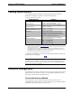
Ethernet OEM Module Crestron eServer™ "Select Web Pages" Dialog Box The "Open" dialog box appears so that a web page can be selected. Browse to the desired directory, select the appropriate web page, and click OK to initiate transfer. The "Transfer In Progress…" dialog box appears to reveal the status of the transfer. The user has the option to cancel the transfer at any time. Otherwise the transfer of web pages to the eServer should conclude successfully.
Crestron eServer™ Ethernet OEM Module Appendix C: Uploading a SIMPL+ Program Use the Viewport to upload a SIMPL+ program to the CEN-OEM. Connect the COM IN port of the eServer to the desired COM port of the PC. Verify communication parameters and be sure the eServer power pack is connected and supplying power to the device. Depress ENTER on the keyboard. If the Viewport responds with ">", communications is verified. From Viewport, select File Transport | Send SIMPL+ Program to the CEN-OEM.
Ethernet OEM Module Crestron eServer™ Glossary of Terms Browser A browser is a software program that allows you to view and interact with various kinds of Internet resources available on the World Wide Web. A browser is commonly called a web browser. CIP Crestron Internet Protocol (CIP) allows Crestron IP devices to communicate with each other. CNX Control System A CNX control system is any Crestron control processor in the CNX product line.
Crestron eServer™ Ethernet OEM Module general structure of various kinds of documents linked together on the World Wide Web. IP Address An IP (Internet Protocol) address is a numeric code that uniquely identifies a particular device (i.e., computer) on the Internet. Just as a street address identifies the location of a home or office, every computer or network on the Internet has a unique address, too. Internet addresses are assigned by an organization called InterNIC.
Ethernet OEM Module Crestron eServer™ Packet A packet is a chunk of information sent over a network. Each packet contains the address of origin, the address of its destination, and information about how to reunite with other related packets. This process allows packets from many different locations to co-mingle on the same lines and be sorted and directed to different routes by special machines along the way.
Crestron eServer™ Ethernet OEM Module if directly connected by computer. An Internet account is needed to be able to use a telnet program. URL An acronym for Uniform Resource Locator, a URL is the address for a resource or site (usually a directory or file) on the World Wide Web and the convention that web browsers use for locating files and other remote services.