Crestron TPS-12G/15G/17G-QM Isys® G-Series Touchpanels with ® QuickMedia Transport Technology Operations Guide
This document was prepared and written by the Technical Documentation department at: Crestron Electronics, Inc. 15 Volvo Drive Rockleigh, NJ 07647 1-888-CRESTRON All brand names, product names and trademarks are the property of their respective owners. ©2009 Crestron Electronics, Inc.
Crestron TPS-12G/15G/17G-QM Isys® G-Series Touchpanels Contents Isys® G-Series Touchpanels: TPS-12G/15G/17G-QM 1 Introduction ............................................................................................................................... 1 Features and Functions ................................................................................................ 2 Applications.................................................................................................................
Crestron TPS-12G/15G/17G-QM Isys® G-Series Touchpanels ® Isys G-Series Touchpanels: TPS-12G/15G/17G-QM Introduction For simplicity within this guide, the Crestron® Isys® G-Series touchpanels are referred to as TPS-12G/15G/17G-QM, except where noted. Crestron Isys G-Series touchpanels deliver a higher level of performance with dual window video, RGB and HDTV display to meet the demands of today’s sophisticated control and automation applications.
Isys® G-Series Touchpanels Crestron TPS-12G/15G/17G-QM Features and Functions • • • • • • • • • • • • • • 12, 15 and 17 inch active matrix touchscreen displays 24-bit Isys graphics Screen resolutions: TPS-12G-QM 800 x 600, TPS-15G-QM 1024 x 768, TPS-17G-QM: 1280 x 768 Synapse™ image rendering algorithm Windows® SideShow™ enabled DNav dynamic menu objects Dual-window full-motion video, HDTV and RGB display* Interactive annotation capability Built-in biamplified speaker system and microphone* QuickMedia® A
Isys® G-Series Touchpanels Crestron TPS-12G/15G/17G-QM Touch-the-PC Crestron exclusive “Touch-the-PC” technology allows real-time touchpanel navigation of any Windows PC through a direct high-speed serial connection. Interactive Annotation Built-in annotation capability allows presenters to write or draw over computer and video images right on the touchscreen using a finger, stylus or mouse. Moving images can also be frozen onscreen to allow annotation over a still picture.
Isys® G-Series Touchpanels Crestron TPS-12G/15G/17G-QM Functional Tiltcase Design The stylish tiltcase housing allows smooth tilt adjustment from 45 to 90 degrees and features an integral cable strain relief system and rear cover to secure and hide the connections at the back of the touchpanel. Five backlit pushbuttons are also provided, allowing for quick access to commonly used functions. 4 • Isys® G-Series Touchpanels: TPS-12G/15G/17G-QM Operations Guide – DOC.
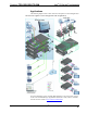
Crestron TPS-12G/15G/17G-QM Isys® G-Series Touchpanels Applications The following diagram shows a TPS-12G/15G/17G-QM in a lecture hall application. TPS-12G/15G/17G-QM in a Lecture Hall Application (TPS-15G-QM Shown) For more information on this and other QM applications, refer to the latest revision of the Crestron MediaManager Applications Guide (Doc. 6244), which is available from the Crestron website (www.crestron.com/manuals). Operations Guide – DOC.
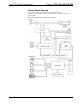
Isys® G-Series Touchpanels Crestron TPS-12G/15G/17G-QM Internal Block Diagram The following diagram represents the switching abilities of the TPS-12G/15G/17G-QM. The diagram depicts the video, audio and connectivity paths available. Internal Block Diagram of the TPS-12G/15G/17G-QM 6 • Isys® G-Series Touchpanels: TPS-12G/15G/17G-QM Operations Guide – DOC.
Isys® G-Series Touchpanels Crestron TPS-12G/15G/17G-QM Specifications Specifications for the TPS-12G/15G/17G-QM are listed in the following table. TPS-12G/15G/17G-QM Specifications SPECIFICATION DETAILS Touchscreen Display Display Type TFT active matrix color LCD Size TPS-12G-QM: 12 inch (30.5 cm) diagonal TPS-15G-QM: 15 inch (38.1 cm) diagonal TPS-17G-QM: 17 inch (43.
Isys® G-Series Touchpanels Crestron TPS-12G/15G/17G-QM TPS-12G/15G/17G-QM Specifications (Continued) SPECIFICATION Video/RGB DETAILS 2 Signal Types RGB and auto-detecting composite, S-video or component video Formats SDTV 480i (NTSC) & 576i (PAL), EDTV 480p & 576p, HDTV 720p & 1080i; RGB (VGA) up to UXGA 1600 x 1200 Color Depth 24-bit, 16.
Isys® G-Series Touchpanels Crestron TPS-12G/15G/17G-QM TPS-12G/15G/17G-QM Specifications (Continued) SPECIFICATION DETAILS Dimensions Height TPS-12G-QM: 12.45 in (31.62 cm) TPS-15G-QM: 14.17 in (36.00 cm) TPS-17G-QM: 14.17 in (36.00 cm) Width TPS-12G-QM: 12.85 in (32.64 cm) TPS-15G-QM: 14.94 in (37.95 cm) TPS-17G-QM: 17.64 in (44.79 cm) Depth 13.75 in (34.91 cm) TPS-12G-QM: 13.8 lbs (6.2 kg) TPS-15G-QM: 15.2 lbs (6.9 kg) TPS-17G-QM: 19.4 lbs (8.
Isys® G-Series Touchpanels Crestron TPS-12G/15G/17G-QM Physical Description This section provides information on the connections, controls and indicators available on your TPS-12G/15G/17G-QM. TPS-12G-QM Physical View 10 • Isys® G-Series Touchpanels: TPS-12G/15G/17G-QM Operations Guide – DOC.
Isys® G-Series Touchpanels Crestron TPS-12G/15G/17G-QM TPS-15G-QM Physical View TPS-17G-QM Physical View Operations Guide – DOC.
Isys® G-Series Touchpanels Crestron TPS-12G/15G/17G-QM NOTE: In the following illustrations, numbers separated by a diagonal or horizontal line represent differing dimensions between the TPS-12G-QM and TPS-15G-QM (or TPS-12G-QM, TPS-15G-QM and TPS-17G-QM) units. TPS-12G/15G-QM Overall Dimensions (Front View) 12.85 in (32.64 cm) 14.94 in (37.95 cm) 10.43 in (26.49 cm) 11.94 in (30.33 cm) 12.45 in (31.62 cm) 14.17 in (36.00 cm) 11.30 in (28.71 cm) TPS-17G-QM Overall Dimensions (Front View) 17.
Isys® G-Series Touchpanels Crestron TPS-12G/15G/17G-QM TPS-12G/15G/17G-QM Overall Dimensions (Side View) 12.45 in (31.62 cm) 14.17 in (36.00 cm) 14.17 in (36.00 cm) 13.75 in (34.91 cm) NOTE: The TPS-12G/15G/17G touchpanels share an identical base unit. 7.40 in (18.80 cm) 10.10 in (25.65 cm) Operations Guide – DOC.
Isys® G-Series Touchpanels Crestron TPS-12G/15G/17G-QM TPS-12G/15G/17G-QM Buttons 1 TPS-12G/15G/17G-QM Connectors 2 3 4 5 6 7 8 14 • Isys® G-Series Touchpanels: TPS-12G/15G/17G-QM 9 10 Operations Guide – DOC.
Isys® G-Series Touchpanels Crestron TPS-12G/15G/17G-QM Connectors, Controls & Indicators # CONNECTORS1, CONTROLS & INDICATORS 1 BUTTONS2 2 HEADPHONES3 3 RS-232 DESCRIPTION (4) Backlit “hard key” buttons, programmable (1) Backlit hard reset button, reboots the touchpanel (1) 3.5 mm TRS mini phone jack; Output power: 12 mW per channel; Minimum impedance: 32 Ω (1) 6-pin RJ-11 female; Computer console, touch output or mouse/touch input port; Bidirectional RS-232 up to 115.
Isys® G-Series Touchpanels Crestron TPS-12G/15G/17G-QM Connectors, Controls & Indicators (Continued) # CONNECTORS1, CONTROLS & INDICATORS 6 24 VDC4, 5 7 NET4 Four-position terminal block connector, Cresnet slave port; Connects to Cresnet control network. 24: Power (24 Volts DC) Y: Data Z: Data G: Ground 8 USB (2) USB Type A female, USB 1.1 ports for mouse or touchscreen input 1 2 3 4 9 MEMORY EXP./ PC CARD (A – B) DESCRIPTION (1) 2.
Isys® G-Series Touchpanels Crestron TPS-12G/15G/17G-QM Connectors, Controls & Indicators (Continued) # CONNECTORS1, CONTROLS & INDICATORS DESCRIPTION 10 QM IN 1 & 26 (1 each) 8-wire RJ-45 female, QuickMedia input port; Signal types: Dynamically configurable under system control as: 1 8 1 8 1 8 • (1) RGB input with stereo program audio and (2) mic channels or • (1) Auto-detecting component (YPbPr), S-video (Y/C) or composite video input with stereo program audio and (2) mic channels RGB format:
Isys® G-Series Touchpanels Crestron TPS-12G/15G/17G-QM 4. The TPS-12G-QM can be powered via the 24 VDC jack or the NET port. Be sure to use a Crestron approved power supply as another may cause damage. The TPS-17G-QM connects to the Cresnet control network and remote power supply via the TPS-17G-QM/-L-IMC Power Interface Module (included with the TPS-17G-QM). CAUTION: Do not connect the TPS-17G-QM directly to the Cresnet network bus. 5.
Isys® G-Series Touchpanels Crestron TPS-12G/15G/17G-QM Industry Compliance As of the date of manufacture the TPS-12G/15G/17G-QM has been tested and found to comply with specifications for CE marking and standards per EMC and Radiocommunications Compliance Labelling. Federal Communications Commission (FCC) Compliance Statement This device complies with part 15 of the FCC rules.
Isys® G-Series Touchpanels Crestron TPS-12G/15G/17G-QM Setup Network Wiring When wiring the network, consider the following: • Use Crestron Certified Wire. • Use Crestron power supplies for Crestron equipment. • Provide sufficient power to the system. CAUTION: Insufficient power can lead to unpredictable results or damage to the equipment. Please use the Crestron Power Calculator to help calculate how much power is needed for the system (www.crestron.com/calculators).
Isys® G-Series Touchpanels Crestron TPS-12G/15G/17G-QM NOTE: Do not untwist the two wires in a single pair for more than 1/3-1/2” (0.84-1.27 cm) when making a connection. The twists are critical to canceling out interference between the wires. The aggregate cable length of a signal path originating at a QM transmitter and terminating at the TPS-12G/15G/17G-QM must not exceed 450 feet (137 meters). Video signals may experience a loss of quality over very long lengths of cable.
Isys® G-Series Touchpanels Crestron TPS-12G/15G/17G-QM QM Network Topology Origination Points Endpoints Midpoints QM QM QM-TX QM QM-MD7x2 QM TPS-12G/15G/17G-QM QM-MD7x2 QM QM-FTDC TPS-12G/15G/17G-QM QM QM-WMC The TPS-12G/15G/17G-QM is not a switcher, but a transmitter/endpoint.
Crestron TPS-12G/15G/17G-QM Isys® G-Series Touchpanels Identity Code Net ID The Net ID of the TPS-12G/15G/17G-QM has been factory set to 03. The Net IDs of multiple TPS-12G/15G/17G-QM devices in the same system must be unique. The NET ID is set using the internal setup menu (refer to “Interface Menu” on page 28). Net ID may also be set from a personal computer (PC) via the Crestron Toolbox™ (refer to “Establishing Communication” which starts on page 56).
Isys® G-Series Touchpanels Crestron TPS-12G/15G/17G-QM MAIN MENU Calibration Menu CALIBRATION MENU Touch Perform Calibration. The message “Touch Upper Left” appears centered on the panel with a cross hair in the upper left corner. Touch the center of the cross hair in the corner of the screen to initiate calibration. Another message, “Touch Upper Right”, appears with a cross hair in the correct corner.
Isys® G-Series Touchpanels Crestron TPS-12G/15G/17G-QM hair in the corner of the screen. A final message, “Touch Lower Right”, appears with a cross hair in the correct corner. Touch the center of the cross hair in the corner of the screen to conclude calibration and return to the CALIBRATION MENU. NOTE: When touching the screen during calibration, be as accurate as possible. Use the tip of a capped pen or the eraser end of a pencil.
Isys® G-Series Touchpanels Crestron TPS-12G/15G/17G-QM controls allow you to select the speed at which screen and backlight levels change when you select a different screen or backlight brightness. Touch Return to go back to the SETUP MENU. ADVANCED OPTIONS MENU Touch Graphics Options to enter the GRAPHICS MENU. GRAPHICS MENU 26 • Isys® G-Series Touchpanels: TPS-12G/15G/17G-QM Operations Guide – DOC.
Isys® G-Series Touchpanels Crestron TPS-12G/15G/17G-QM The GRAPHICS MENU provides controls for Dynamic Graphics Loading Icon Position and for hiding the loading icon. There are also Page Flips use Backbuffer Enable and Disable buttons. When enabled, new pages are drawn in the backbuffer and displayed when fully drawn. When disabled, new pages will be drawn on the screen from top to bottom. Touch Return to go back to the ADVANCED OPTIONS MENU.
Isys® G-Series Touchpanels Crestron TPS-12G/15G/17G-QM Key Backlight Settings The Key Backlight Settings menu provides – and + controls to adjust Current Key Backlight Level, High Brightness Level, Medium Brightness Level and Low Brightness Level. The Press To Trigger Level Now buttons allow for immediate setting of key brightness level to HIGH, MEDIUM or LOW. Touch Return to go back to the ADVANCED OPTIONS MENU.
Crestron TPS-12G/15G/17G-QM Isys® G-Series Touchpanels INTERFACE MENU Two buttons adjacent to the hexadecimal display, DOWN and UP, decrease and increase the Net ID by one, respectively. The four buttons at the bottom define how the RS-232 port can be used; as a console port (i.e.
Isys® G-Series Touchpanels Crestron TPS-12G/15G/17G-QM Ethernet Setup Menu Touching the Ethernet button on the SETUP MENU displays the ETHERNET SETUP MENU. This menu provides information on the Current IP Address and Ethernet link status, along with buttons for DHCP Enable and Disable and, when DHCP is disabled, Static IP Options. The enable/disable Ethernet feature is provided on the INTERFACE MENU. Ethernet settings are made through Crestron Toolbox.
Isys® G-Series Touchpanels Crestron TPS-12G/15G/17G-QM ETHERNET SETUP MENU (DHCP Disabled) Each of the Static IP Options has its own menu, as shown in the illustrations below and on the following page. ETHERNET STATIC IP SETTINGS Operations Guide – DOC.
Isys® G-Series Touchpanels Crestron TPS-12G/15G/17G-QM ETHERNET DNS SETTINGS ETHERNET WINS SETTINGS 32 • Isys® G-Series Touchpanels: TPS-12G/15G/17G-QM Operations Guide – DOC.
Crestron TPS-12G/15G/17G-QM Isys® G-Series Touchpanels RS-232 Menu The touchpanel allows for one of four RS-232 communication modes: • Console (i.e.
Isys® G-Series Touchpanels Crestron TPS-12G/15G/17G-QM General Audio Setup To open the GENERAL AUDIO SETUP menu touch Audio on the SETUP MENU. The GENERAL AUDIO SETUP menu offers a series of buttons that adjust the volume level as indicated by the gauges. Speaker Volume, Key Click Volume, WAV Volume and Headphone Volume are independently adjustable. Controls for Bass, Treble and Headphone Balance are also provided. The Play Test WAV File button plays a short audio file.
Isys® G-Series Touchpanels Crestron TPS-12G/15G/17G-QM General Audio Setup Details (Continued) GENERAL AUDIO SETUP SCREEN CONTROL DESCRIPTION Speaker Volume The volume of both audio inputs (key click and WAV) is affected by the Speaker Volume control. If the Speaker Volume control is set to 100% the volume for any audio input is at maximum. If the Speaker Volume is set to 0% the value of all audio inputs is overridden and the touchpanel is silent.
Isys® G-Series Touchpanels Crestron TPS-12G/15G/17G-QM QM AUDIO INPUT SETUP Refer to the following table for additional QM AUDIO INPUT SETUP menu details. QM Audio Input Setup Details QM AUDIO INPUT SETUP SCREEN CONTROL DESCRIPTION INPUT SELECT QM AUDIO 1 QM AUDIO 2 Selects QM audio source. This selection determines whether QM 1 or QM 2 inputs are displayed. Restore Default Audio Settings Returns audio settings to their factory defaults.
Isys® G-Series Touchpanels Crestron TPS-12G/15G/17G-QM QM AUDIO OUTPUT SETUP Refer to the following table for additional QM AUDIO OUTPUT SETUP menu details. QM Audio Output Setup Details QM AUDIO OUTPUT SETUP SCREEN CONTROL DESCRIPTION Program Gain Adjusts the level of the QM output with the – and + buttons. Transmit QM ID Allows transmission of touchpanel’s QM ID for use in QM systems utilizing auto compensation*. Manual will transmit a specific QM ID, adjustable with the Down and Up Buttons.
Isys® G-Series Touchpanels Crestron TPS-12G/15G/17G-QM QM Setup To open the QM SETUP menu, touch QM on the SETUP MENU. The QM SETUP menu offers controls for selecting QM Audio Input, QM Setup channels and video type for each QM Setup channel. After these parameters have been set, touch Return to go back to the SETUP MENU. QM SETUP Refer to the following table for additional QM SETUP menu details.
Isys® G-Series Touchpanels Crestron TPS-12G/15G/17G-QM QM Setup Details (Continued) QM SETUP SCREEN CONTROL Setup QM 2 DESCRIPTION Displays the QM 2 SETUP menu. By default the QM 2 SETUP menu displays video controls Peak and Boost in the lower right quadrant of the menu. Video Pressing this before pressing the Setup QM 2 button will open the QM 2 SETUP menu in Video mode. S-Video Pressing this before pressing the Setup QM 2 button will open the QM 2 SETUP menu in S-Video mode.
Isys® G-Series Touchpanels Crestron TPS-12G/15G/17G-QM QM 1 Setup Details QM 1 SETUP SCREEN CONTROL DESCRIPTION Auto Compensation* Disable Turns off auto compensation. Auto Compensation* Enable Turns on auto compensation. When auto compensation is on, the QM receiving device uses the auto compensation data received from the QM transmitter. Video Puts the menu in Video mode so that you can adjust the Peak, Boost, Skew Red, Skew Green and Skew Blue signals for video.
Isys® G-Series Touchpanels Crestron TPS-12G/15G/17G-QM Video Setup These touchpanels can display two fully scalable and movable, full motion video windows, each supporting standard video, HDTV and high-resolution RGB signals from external AV and computer sources. These units use auto-detect for composite, S-video or component RGBHV. They support SDTV (NTSC and PAL), EDTV, HDTV and RGB (VGA) up to UXGA (1600 x 1200). Two video inputs provide for connectivity to QuickMedia.
Isys® G-Series Touchpanels Crestron TPS-12G/15G/17G-QM Video Setup Details (Continued) VIDEO SETUP SCREEN CONTROL DESCRIPTION Setup Video 1 (Continued) S-Video Pressing this before pressing the Setup Video 1 button will open the VIDEO 1 SETUP menu in S-Video mode. Component Pressing this before pressing the Setup Video 1 button will open the VIDEO 1 SETUP menu in Component mode. RGB Pressing this before pressing the Setup Video 1 button will open the VIDEO 1 SETUP menu in RGB mode.
Isys® G-Series Touchpanels Crestron TPS-12G/15G/17G-QM VIDEO 1 SETUP (RGB Size & Position shown) Refer to the following table for additional VIDEO 1 SETUP details. Video 1 Setup Details – Video, S-Video, Component and RGB VIDEO 1 SETUP SCREEN CONTROLS DESCRIPTION QM Signal Indicates the presence of a QM signal. Video Preset Displays the current Video Preset number. Saved presets can also be called up using this control. The – and + buttons decrement and increment the displayed value.
Isys® G-Series Touchpanels Crestron TPS-12G/15G/17G-QM Video 1 Setup Details – Video, S-Video, Component and RGB (Continued) VIDEO 1 SETUP SCREEN CONTROLS DESCRIPTION Color Control (Continued) Blue1, 2 Overscan3 1. 2. 3. Adjusts the amount of blue in the video signal. Available when the RGB Color button is selected. These controls adjust the amount of video information at the edges of the image. This part of the video picture is usually beyond the display capabilities of the screen.
Isys® G-Series Touchpanels Crestron TPS-12G/15G/17G-QM Diagnostics Menu Touch Diagnostics on the MAIN MENU to access the DIAGNOSTICS MENU, which contains controls for diagnostic tools. The diagnostic tools should only be used under supervision from a Crestron customer service representative during telephone support. The options available from the DIAGNOSTICS MENU are numeric in nature and their interpretation is beyond the scope of this manual.
Isys® G-Series Touchpanels Crestron TPS-12G/15G/17G-QM Hardware Connections for the TPS-12G/15G/17G-QM HEADPHONES 24VDC: AC POWER PACK USB: FROM MOUSE OR EXTERNAL TOUCH DEVICE GROUND RS-232: TO COMPUTER OR OTHER RS-232 DEVICE LAN: 10BASE-T/100BASE-TX HIGH SPEED ETHERNET TO LAN COMPACT FLASH CARD and PC CARD SLOTS (PC CARD SLOTS RESERVED FOR FUTURE APPLICATIONS) QM OUT: QUICKMEDIA VIDEO, AUDIO & MIC OUTPUT OVER CAT5 QM IN: QUICKMEDIA VIDEO, AUDIO & MIC INPUT OVER CAT5 QM IN: QUICKMEDIA VIDEO, AUDIO
Isys® G-Series Touchpanels Crestron TPS-12G/15G/17G-QM NOTE: Crestron recommends an independent power supply for the touchpanel. QM-TX QuickMedia Transmitter The QM-TX QuickMedia Transmitter can be used to connect a video or audio source to a QuickMedia network without a locally available QM transmitter (such as the QM-WMC). The QM-TX accepts composite video, S-video, component video, RGBHV and audio signals.
Isys® G-Series Touchpanels Crestron TPS-12G/15G/17G-QM Tilt Angle Tension Adjustment Use a 5/32 inch socket (not included) with a hex drive key (Allen wrench) to increase or decrease pivot tension at the base of the touchscreen. Turning the key clockwise increases tension, counterclockwise decreases tension.
Crestron TPS-12G/15G/17G-QM Isys® G-Series Touchpanels Programming Software Have a question or comment about Crestron software? Answers to frequently asked questions (FAQs) can be viewed in the Online Help section of the Crestron website. To post a question or view questions you have submitted to Crestron’s True Blue Support, log in at http://support.crestron.com. First-time users will need to establish a user account.
Isys® G-Series Touchpanels Crestron TPS-12G/15G/17G-QM Locating the TPS-12G/15G/17G-QM(Cresnet) in the Device Library • To incorporate the TPS-12G/15G/17G-QM (Ethernet) into the system, drag the TPS-12G/15G/17G-QM from the Touchpanels | Touchpanels (Ethernet) folder of the Device Library and drop it in the System Views.
Isys® G-Series Touchpanels Crestron TPS-12G/15G/17G-QM NOTE: There is both an Ethernet device in Slot 8 and a Cresnet device in Slot 9 of the following illustration. It is possible to have both types of device attached to a control system so long as the control system has either a built-in or expansion Ethernet interface. C2Net Device, Slot 8 and 9 • Additional TPS-12G/15G/17G-QM devices are assigned different Net ID (for Cresnet devices) or IP ID (for Ethernet devices) numbers as they are added.
Isys® G-Series Touchpanels Crestron TPS-12G/15G/17G-QM “TPS-17G-QM (Ethernet) Device Settings” Window (Same as window for TPS-12G-QM and TPS-15G-QM) • Program Manager The ID code specified in the SIMPL Windows program must match the Net ID or IP ID of each unit. Program Manager is the view where programmers “program” a Crestron control system by assigning signals to symbols. The symbol can be viewed by double clicking on the icon or dragging it into Detail View.
Isys® G-Series Touchpanels Crestron TPS-12G/15G/17G-QM only accept the following WAV file format: PCM, 8-bit, 8 kHz, mono. For more information about how to use Sound Recorder, refer to its User’s Guide and extensive help information provided with the software. Also refer to the help file in VT Pro-e to learn how to use its audio tool, Sound Manager, to attach WAV files to a touchpanel project. Pre-recorded WAV files for voice prompts and responses are available from Crestron.
Isys® G-Series Touchpanels Crestron TPS-12G/15G/17G-QM 32-bit graphics to a minimum (e.g. for a family photo, etc.), you can create a sophisticated project that will fit in the memory space provided and have the touchpanel remain very responsive. Relationship of Bits to Colors NUMBER OF BITS 1 bit NUMBER OF COLORS Black and White 2 bits 4 Colors 4 bits 16 Colors 8 bits 256 Colors 16 bits 65,536 Colors (Highcolor) 24 bits 16.7 million Colors (Truecolor) 32 bits 16.
Isys® G-Series Touchpanels Crestron TPS-12G/15G/17G-QM Pushbutton Programming Four of the buttons can be programmed to access any frequently used command. Each button has a permanently fixed digital join number. The sequence of digital join numbers is (left to right) 1 through 4. Refer to the following illustration for their assigned join numbers. A description for each button signal is described in the SIMPL Windows help file (F1).
Isys® G-Series Touchpanels Crestron TPS-12G/15G/17G-QM Uploading and Upgrading Crestron recommends using the latest programming software and that each device contains the latest firmware to take advantage of the most recently released features. However, before attempting to upload or upgrade it is necessary to establish communication. Once communication has been established, files (for example, programs, projects or firmware) can be transferred to the control system (and/or device).
Crestron TPS-12G/15G/17G-QM Isys® G-Series Touchpanels address book entry of the control system that is connected to the TPS-12G/15G/17G-QM. • Display the TPS-12G/15G/17G-QM’s “System Info” window (click the icon); communications are confirmed when the device information is displayed. TCP/IP NOTE: Required for operation with a Crestron control system. Ethernet Communication PC RUNNING CRESTRON TOOLBOX ETHERNET TPS-12G/15G/17G-QM • Establish serial communication between TPS-12G/15G/17G-QM and PC.
Isys® G-Series Touchpanels • Crestron TPS-12G/15G/17G-QM Select Functions | Firmware… to upgrade the TPS-12G/15G/17G-QM firmware. Program Checks Actions that can be performed on the TPS-12G/15G/17G-QM vary depending on whether it is connected via Cresnet or Ethernet. Cresnet Connections Ethernet Connections For Cresnet connections, display the network device tree (Tools | Network Device Tree) to show all network devices connected to the control system.
Isys® G-Series Touchpanels Crestron TPS-12G/15G/17G-QM Problem Solving Troubleshooting The following table provides corrective action for possible trouble situations. If further assistance is required, please contact a Crestron customer service representative. TPS-12G/15G/17G-QM Troubleshooting TROUBLE POSSIBLE CAUSE(S) CORRECTIVE ACTION TPS-12G/15G/17G-QM does not function. TPS-12G/15G/17G-QM is not receiving power. Verify power to unit. Use only Crestron power supplies for Crestron equipment.
Isys® G-Series Touchpanels Crestron TPS-12G/15G/17G-QM TPS-12G/15G/17G-QM Troubleshooting (Continued) TROUBLE POSSIBLE CAUSE(S) CORRECTIVE ACTION Wrong VisionTools Pro-e or SIMPL Windows programs. Verify correct programs. Verify proper video set up. Incorrect input connection. Verify video input and QM connections. IP address not correct (LAN green and amber LEDs are off). Assign correct IP address to TPS-12G/15G/17G-QM. IP mask not correct (LAN green and amber LEDs are on).
Isys® G-Series Touchpanels Crestron TPS-12G/15G/17G-QM chain. If the unit is home-run from a Crestron system power supply network port, the Cresnet power usage of that unit is the Cresnet power usage of the entire run. The wire gauge and the Cresnet power usage of the run should be used in the following equation to calculate the cable length value on the equation’s left side. Cable Length Equation 40,000 L< RxP Where: L = Length of run (or chain) in feet R = 6 Ohms (Crestron Certified Wire: 18 AWG (0.
Isys® G-Series Touchpanels Crestron TPS-12G/15G/17G-QM Further Inquiries If you cannot locate specific information or have questions after reviewing this guide, please take advantage of Crestron's award winning customer service team by calling Crestron at 1-888-CRESTRON [1-888-273-7876]. You can also log onto the online help section of the Crestron website (www.crestron.com/onlinehelp) to ask questions about Crestron products.
Isys® G-Series Touchpanels Crestron TPS-12G/15G/17G-QM Software License Agreement This License Agreement (“Agreement”) is a legal contract between you (either an individual or a single business entity) and Crestron Electronics, Inc. (“Crestron”) for software referenced in this guide, which includes computer software and as applicable, associated media, printed materials and “online” or electronic documentation (the “Software”).
Isys® G-Series Touchpanels Crestron TPS-12G/15G/17G-QM If You are a business or organization, You agree that upon request from Crestron or its authorized agent, You will within thirty (30) days fully document and certify that use of any and all Software at the time of the request is in conformity with Your valid licenses from Crestron of its authorized agent.
Isys® G-Series Touchpanels Crestron TPS-12G/15G/17G-QM Return and Warranty Policies Merchandise Returns / Repair Service 1. No merchandise may be returned for credit, exchange or service without prior authorization from CRESTRON. To obtain warranty service for CRESTRON products, contact an authorized CRESTRON dealer. Only authorized CRESTRON dealers may contact the factory and request an RMA (Return Merchandise Authorization) number.
Crestron Electronics, Inc. 15 Volvo Drive Rockleigh, NJ 07647 Tel: 888.CRESTRON Fax: 201.767.7576 www.crestron.com Operations Guide – DOC. 6415B (2013896) 01.09 Specifications subject to change without notice.