Crestron TPS-GA-TPI Isys® G-Series Touchpanel Interface Operations Guide
This document was prepared and written by the Technical Documentation department at: Crestron Electronics, Inc. 15 Volvo Drive Rockleigh, NJ 07647 1-888-CRESTRON All brand names, product names and trademarks are the property of their respective owners. ©2007 Crestron Electronics, Inc.
Crestron TPS-GA-TPI Isys® G-Series Touchpanel Interface Contents Isys® G-Series Touchpanel Interface: TPS-GA-TPI 1 Introduction ............................................................................................................................... 1 Features and Functions ................................................................................................ 1 Internal Block Diagram ...............................................................................................
Isys® G-Series Touchpanel Interface Crestron TPS-GA-TPI ® Isys G-Series Touchpanel Interface: TPS-GA-TPI Introduction Features and Functions • • • • • • • High-performance touchpanel interface. 24-Bit Isys® graphics. Synapse image rendering algorithm. Dual-window HD video and RGB display. Built-in real-time annotation. High-speed Ethernet and Cresnet® communications. Single-space rack-mountable.
Isys® G-Series Touchpanel Interface Crestron TPS-GA-TPI Isys® The TPS-GA-TPI offers vibrant 24-bit color depth with 8-bit alpha channel transparency to produce incredible 3D graphics and high-res images. The Isys engine supports dynamic graphics and text, full-motion animations, multimode objects, and PNG translucency - all with astonishing speed. Synapse™ Crestron's exclusive Synapse Image Rendering Algorithm enables system programmers to produce amazing graphics - faster and easier.
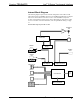
Isys® G-Series Touchpanel Interface Crestron TPS-GA-TPI Internal Block Diagram The following diagram represents the internal configuration of the TPS-GA-TPI. These units feature two RGBHV inputs to receive RGBS and RGsB from a computer and two sets of three BNC connectors to receive video and HDTV (composite, S-video, and component) inputs. There is also a QM output for connection to a QM receiver or switcher. For more information, refer to “QuickMedia Wiring” on page 12.
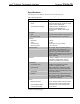
Isys® G-Series Touchpanel Interface Crestron TPS-GA-TPI Specifications Specifications for the TPS-GA-TPI are listed in the following table. TPS-GA-TPI Specifications SPECIFICATION DETAILS Device Support Mouse Microsoft Serial Mouse, Kensington Serial Mouse, Generic USB Mouse Touchscreen/Pen Display 3M Dynapro SC3, 3M Microtouch, CyberTouch, DisplayMate, Elo TouchSystems, SMART Technologies, Wacom1 Processor CPU 32-bit Freescale ColdFire® Microprocessor Processing Speed 410 MIPS (Dhrystone 2.
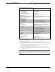
Isys® G-Series Touchpanel Interface Crestron TPS-GA-TPI TPS-GA-TPI Specifications (Continued) SPECIFICATION DETAILS 3 Power Requirements Power Supply (sold separately) Cresnet Power Usage PW-2420RU Default NET ID 03 Minimum 2-Series Control System Update File 4, 5, 6 Version 3.155.1143 or later 45 Watts (1.
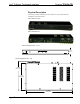
Isys® G-Series Touchpanel Interface Crestron TPS-GA-TPI Physical Description This section provides information on the connections, controls and indicators available on your TPS-GA-TPI. TPS-GA-TPI Front View TPS-GA-TPI Rear View TPS-GA-TPI Physical View – Front 1.70 in (4.32 cm) TPS-GA-TPI Physical View – Top 10.68 in (27.13 cm) 9.97 in (25.32 cm) 17.03 in (43.26 cm) 6 • Isys® G-Series Touchpanel Interface: TPS-GA-TPI Operations Guide – DOC.
Isys® G-Series Touchpanel Interface Crestron TPS-GA-TPI TPS-GA-TPI Physical View – Rear Location of Connections, Controls and Indicators (Front) 1 2 Location of Connections, Controls and Indicators (Rear) 5 3 4 7 6 9 13 11 8 10 12 14 Connectors, Controls & Indicators # CONNECTORS1, CONTROLS & INDICATORS DESCRIPTION 1 PWR LED (1) Green LED, indicates DC power applied to NET port or 24VDC jack. 2 RESET BUTTON (1) Recessed miniature pushbutton, reboots the touchpanel interface.
Isys® G-Series Touchpanel Interface Crestron TPS-GA-TPI Connectors, Controls & Indicators (Continued) # CONNECTORS1, CONTROLS & INDICATORS DESCRIPTION 3 RGBHV OUT (1) DB15 HD female, RGB (VGA) output; Analog Format: RGBHV; Output Resolution: Software programmable 800x600, 1024x768, 1280x768, 1366x768, 1152x864, 1280x1024 Sync Output Type: RGBHV Sync Output Level: TTL, 4.
Isys® G-Series Touchpanel Interface Crestron TPS-GA-TPI Connectors, Controls & Indicators (Continued) # CONNECTORS1, CONTROLS & INDICATORS DESCRIPTION 7 24VDC3 (1) 2 mm barrel DC power jack, 24 Volt DC power input; (PW-2420RU power supply sold separately). 8 NET3 Four-position terminal block connector for data and power. Connects to Cresnet control network. Pin 1 (24) Power Pin 2 (Y) Data Pin 3 (Z) Data Pin 4 (G) Ground (2) USB 1.
Isys® G-Series Touchpanel Interface Crestron TPS-GA-TPI Connectors, Controls & Indicators (Continued) # CONNECTORS1, CONTROLS & INDICATORS DESCRIPTION 13 RGBHV IN (1 – 2) (2) DB15HD female, RGB (VGA) inputs; Analog Formats: RGBHV, RGBS and RGSB Input Resolution, Non-interlaced: 640x480 minimum to 1600x1200 maximum; Horizontal Frequency: 31.5 to 100 kHz Vertical Frequency: 60 to 85 Hz (60 Hz limit at 1600x1200) Standard HD15 connector configured to optimize performance.
Isys® G-Series Touchpanel Interface Crestron TPS-GA-TPI 4. The eight-pin RJ-45 QuickMedia transport port accepts CAT5E/CAT6 carrying audio, video and microphone signals. The QM output port conforms to the 568B wiring standard. Refer to the following table for connector pinouts.
Isys® G-Series Touchpanel Interface Crestron TPS-GA-TPI Setup Network Wiring When wiring the network, consider the following: • Use Crestron Certified Wire. • Use Crestron power supplies for Crestron equipment. • Provide sufficient power to the system. CAUTION: Insufficient power can lead to unpredictable results or damage to the equipment. Please use the Crestron Power Calculator to help calculate how much power is needed for the system (http://www.crestron.com/calculators).
Isys® G-Series Touchpanel Interface Crestron TPS-GA-TPI CresCAT-QM Cable CresCAT-QM Cable NOTE: Do not untwist the two wires in a single pair for more than 1/3-1/2” (0.84-1.27 cm) when making a connection. The twists are critical to canceling out interference between the wires. The aggregate cable length of a signal path originating at the TPS-GA-TPI and terminating at QM endpoint such as a TPS-12G/15G-QM-L must not exceed 450 feet (137 meters).
Isys® G-Series Touchpanel Interface Crestron TPS-GA-TPI QM Network Topology Origination Points Endpoints Midpoints QM TPS-GA-TPI QM QM-MD7x2 QM QM TPS-12G/15G-QM-L QM-MD7x2 QM QM-FTDC QM-RX QM QM-WMC The TPS-GA-TPI is an origination point. Therefore, in a QM system, it would be positioned as shown above. Identity Code Net ID The Net ID of the TPS-GA-TPI has been factory set to 03. The Net IDs of multiple TPS-GA-TPI devices in the same system must be unique.
Isys® G-Series Touchpanel Interface Crestron TPS-GA-TPI Upon entering SETUP MODE, the MAIN MENU, as shown in the following illustration, displays four buttons: Touch Screen Calibration, Exit and Run Program, Setup, and Diagnostics. The Exit and Run Program button verifies that all of the setup information has been saved to the EEPROM and displays the main page that has been programmed into your system. The remaining buttons on the MAIN MENU open other menus, which are discussed in subsequent paragraphs.
Isys® G-Series Touchpanel Interface Crestron TPS-GA-TPI Calibration Menu CALIBRATION MENU Touch Touchscreen Calibration on the MAIN MENU and then Perform Calibration on the CALIBRATION MENU. The message “Touch Upper Left” appears centered on the panel with a cross hair in the upper left corner. Touch the center of the cross hair in the corner of the screen to initiate calibration. Another message, “Touch Upper Right”, appears with a cross hair in the correct corner.
Isys® G-Series Touchpanel Interface Crestron TPS-GA-TPI SETUP MENU Interface Menu The TPS-GA-TPI communicates with a control system to activate commands or to display feedback from components within the system. The communication interface must be correctly configured or communication will not occur. To set communication parameters select the Interface button located on the SETUP MENU and display the INTERFACE MENU.
Isys® G-Series Touchpanel Interface Crestron TPS-GA-TPI INTERFACE MENU Two buttons adjacent to the Cresnet ID and its displayed hexadecimal number, Down and Up, decrease and increase the Cresnet ID by one, respectively. The Ethernet Enable and Disable buttons determine the status of the interface’s Ethernet communications. NOTE: The TPS-GA-TPI does not support wireless Ethernet. There may be Ethernet devices (i.e.
Crestron TPS-GA-TPI Isys® G-Series Touchpanel Interface “Establishing Communication”, which starts on page 41 for additional Ethernet setup details. NOTE: The address shown for the Current IP Address is only representative. It does not reflect a real or suggested address. ETHERNET SETUP MENU (STATIC) ETHERNET STATIC IP SETTINGS Operations Guide – DOC.
Isys® G-Series Touchpanel Interface Crestron TPS-GA-TPI ETHERNET DNS SETTINGS ETHERNET WINS SETTINGS Selection of the DHCP Enable button from the ETHERNET SETUP MENU displays the DHCP options Renew and Release. 20 • Isys® G-Series Touchpanel Interface: TPS-GA-TPI Operations Guide – DOC.
Isys® G-Series Touchpanel Interface Crestron TPS-GA-TPI ETHERNET SETUP MENU (DHCP ENABLED) RS-232 Menu The TPS-GA-TPI interface allows for one of four RS-232 communication modes: • Console (i.e., loading TPS-GA-TPI interface projects and firmware) • Touch Output (communication of touch coordinates to an external device) • Mouse Input (allows a mouse to control the interface) • External Touch Input (allows another device to control the interface).
Isys® G-Series Touchpanel Interface Crestron TPS-GA-TPI RS-232 MENU General Audio Setup To open the GENERAL AUDIO SETUP menu, press the Audio button from the SETUP MENU. The GENERAL AUDIO SETUP menu offers a series of buttons that adjust the volume as indicated by the gauges. These controls allow you to precisely control key click, WAV and headphone volume, bass and treble and headphone balance in the audio mix.
Isys® G-Series Touchpanel Interface Crestron TPS-GA-TPI GENERAL AUDIO SETUP MENU Refer to the following table for additional GENERAL AUDIO SETUP menu details. General Audio Setup Details GENERAL AUDIO SETUP SCREEN CONTROLS DESCRIPTION QM Output Displays the QM AUDIO OUTPUT SETUP menu. Play Test WAV File Plays a short WAV audio file. Restore Default Audio Settings Returns the settings on this menu to their factory defaults. Mute A separate Mute button is supplied for each of the volume controls.
Isys® G-Series Touchpanel Interface Crestron TPS-GA-TPI To open the QM AUDIO OUTPUT SETUP menu, press the QM Output button on the GENERAL AUDIO SETUP menu. The QM AUDIO OUTPUT SETUP menu offers a series of buttons that adjust the program gain and Transmit QM ID. The Restore Default Output Settings button returns all audio parameters on this menu to their default settings. Program Gain buttons and Transmit QM ID Manual and Auto buttons are provided to adjust QM audio output.
Isys® G-Series Touchpanel Interface Crestron TPS-GA-TPI Video Setup The TPS-GA-TPI can display two fully-scalable and movable, full motion video windows, each supporting standard video, HDTV and high-resolution RGB signals from external AV and computer sources. These units use auto-detect for composite, S-video, component or RGBHV. They support SDTV (NTSC and PAL), EDTV, HDTV and RGB (VGA) up to UXGA (1600 x 1200). Two video inputs provide signals that can be routed to QM OUT.
Isys® G-Series Touchpanel Interface Crestron TPS-GA-TPI Video Setup Details VIDEO SETUP SCREEN CONTROLS Setup Video 1 DESCRIPTION Displays the VIDEO 1 SETUP menu. By default, the VIDEO 1 SETUP menu displays video controls: Brightness, Contrast, Saturation and Hue on the right side of the menu. Video Pressing this before pressing the Setup Video 1 button will open the VIDEO 1 SETUP menu in Video mode.
Isys® G-Series Touchpanel Interface Crestron TPS-GA-TPI The video menu for RGB controls consists of preset controls, color and size & position submenus. Touching the RGB Color button enables controls for brightness, contrast, red, green, and blue. Touching the RGB Size & Position button enables position, size and phase controls. VIDEO 1 SETUP RGB (Size and position shown) Refer to the following table for additional VIDEO 1 SETUP details.
Isys® G-Series Touchpanel Interface Crestron TPS-GA-TPI Video 1 Setup Details – Video, S-Video, Component and RGB (Continued) VIDEO 1 SETUP SCREEN CONTROLS DESCRIPTION Color Control (Continued) Green1, 2 Adjusts the amount of green in the video signal. Available when the RGB Color button is selected. Blue1, 2 Adjusts the amount of blue in the video signal. Available when the RGB Color button is selected. Overscan3 1. 2. 3.
Isys® G-Series Touchpanel Interface Crestron TPS-GA-TPI Diagnostics Menu The Diagnostics button from the MAIN MENU contains controls for diagnostic tools. The diagnostic tools should only be used under supervision from a Crestron customer service representative during telephone support. The options available from the DIAGNOSTICS MENU are numeric in nature and their interpretation is beyond the scope of this manual.
Isys® G-Series Touchpanel Interface • Crestron TPS-GA-TPI If the rack is provided with stabilizing devices, install the stabilizers before mounting or servicing the unit in the rack. NOTE: If rack mounting is not required, rubber feet are provided for tabletop mounting or stacking. Apply the feet near the corner edges on the underside of the unit. NOTE: Reliable earthing of rack-mounted equipment should be maintained.
Isys® G-Series Touchpanel Interface Crestron TPS-GA-TPI Foot Placement for the TPS-GA-TPI PLACE FEET IN CORNERS Hardware Hookup Make the necessary connections as called out in the illustration that follows this paragraph. Refer to “Network Wiring” on page 12 before attaching the 4-position terminal block connector. Apply power after all connections have been made. When making connections to the TPS-GA-TPI, use Crestron power supplies for Crestron equipment.
Isys® G-Series Touchpanel Interface Crestron TPS-GA-TPI NOTE: Crestron recommends an independent power supply for the TPS-GA-TPI when Cresnet power is not available. NOTE: For optimum performance, Crestron strongly recommends using Crestron Certified CresCAT-QM cable, available from Crestron. Other high-quality/low skew CAT5e/CAT6 wiring may also be used with varying performance.
Isys® G-Series Touchpanel Interface Crestron TPS-GA-TPI Serial Connection 1. Connect the RGBHV OUT to the RGB in on the touchscreen. 2. Connect to the TPS-GA-TPI via USB or TCP/IP communication as described in “Establishing Communication” on page 41. 3. Using the Toolbox Text Console, enter the EXTT command to set the TPS-GA-TPI for the touchscreen you have connected. 4. Using the Toolbox Text Console, enter the TPIMODE command to set the TPS-GA-TPI to the native resolution of the touchscreen.
Isys® G-Series Touchpanel Interface Crestron TPS-GA-TPI Programming Software Have a question or comment about Crestron software? Answers to frequently asked questions (FAQs) can be viewed in the Online Help section of the Crestron website. To post a question or view questions you have submitted to Crestron’s True Blue Support, log in at http://support.crestron.com. First-time users will need to establish a user account.
Isys® G-Series Touchpanel Interface Crestron TPS-GA-TPI Locating the TPS-GA-TPI (Cresnet) in the Device Library • To incorporate the TPS-GA-TPI (Ethernet) into the system, drag the TPS-GA-TPI from the Touchpanels|Touchpanels (Ethernet) folder of the Device Library and drop it in the System Views. Locating the TPS-GA-TPI (Ethernet) in the Device Library • Operations Guide – DOC.
Isys® G-Series Touchpanel Interface Crestron TPS-GA-TPI C2Net Device, Slots 8 and 9 • Additional TPS-GA-TPI devices are assigned different Net ID (for Cresnet devices) or IP ID (for Ethernet devices) numbers as they are added. • If necessary, double click a device to open the “Device Settings” window and change the Net ID or IP ID, as shown in the following figures. “TPS-GA-TPI Cresnet Device Settings” Window 36 • Isys® G-Series Touchpanel Interface: TPS-GA-TPI Operations Guide – DOC.
Isys® G-Series Touchpanel Interface Crestron TPS-GA-TPI “TPS-GA-TPI Ethernet Device Settings” Window • Program Manager The ID code specified in the SIMPL Windows program must match the Net ID or IP ID of each unit. Program Manager is the view where programmers “program” a Crestron control system by assigning signals to symbols. The symbol can be viewed by double clicking on the icon or dragging it into Detail View. Each signal in the symbol is described in the SIMPL Windows help file (F1).
Isys® G-Series Touchpanel Interface Crestron TPS-GA-TPI to its User’s Guide and extensive help information provided with the software. Also refer to the help file in VT Pro-e to learn how to use its audio tool, Sound Manager, to attach WAV files to an interface project. Pre-recorded WAV files for voice prompts and responses are available from Crestron. These files can be stored into and programmed for use in the interfaces directly or may be edited with the Sound Recorder.
Isys® G-Series Touchpanel Interface Crestron TPS-GA-TPI Relationship of Bits to Colors NUMBER OF BITS NUMBER OF COLORS 1 bit Black and White 2 bits 4 Colors 4 bits 16 Colors 8 bits 256 Colors 16 bits 65,536 Colors (Highcolor) 24 bits 16.7 million Colors (Truecolor) 32 bits 16.
Isys® G-Series Touchpanel Interface Crestron TPS-GA-TPI For example, Chinese fonts contain several thousand characters. Other multibyte languages include Japanese and Korean. There are two separate applications with multibyte characters – static text on buttons and indirect text on buttons. No Isys touchpanel or interface firmware changes are required in either case. Indirect text on a button is entered in VT Pro-e and the actual string to be displayed is entered in SIMPL Windows.
Isys® G-Series Touchpanel Interface Crestron TPS-GA-TPI Uploading and Upgrading Crestron recommends using the latest programming software and that each device contains the latest firmware to take advantage of the most recently released features. However, before attempting to upload or upgrade it is necessary to establish communication. Once communication has been established, files (for example, programs, projects or firmware) can be transferred to the control system (and/or device).
Isys® G-Series Touchpanel Interface TCP/IP Communication Crestron TPS-GA-TPI NOTE: Required for operation with a Crestron control system. Ethernet Communication PC RUNNING CRESTRON TOOLBOX ETHERNET TPS-GA-TPI • Establish serial communication between TPS-GA-TPI and PC. • Enter the IP address, IP mask and default router of the TPS-GA-TPI via the Crestron Toolbox (Functions | Ethernet Addressing); otherwise enable DHCP. • Confirm Ethernet connections between TPS-GA-TPI and PC.
Isys® G-Series Touchpanel Interface Crestron TPS-GA-TPI Program Checks Actions that can be performed on the TPS-GA-TPI vary depending on whether it is connected via Cresnet or Ethernet. Cresnet Connections Ethernet Connections For Cresnet connections, display the network device tree (Tools | Network Device Tree) to show all network devices connected to the control system. Right-click on the TPS-GA-TPI to display actions that can be performed on the TPS-GA-TPI.
Isys® G-Series Touchpanel Interface Crestron TPS-GA-TPI Problem Solving Troubleshooting The following table provides corrective action for possible trouble situations. If further assistance is required, please contact a Crestron customer service representative. TPS-GA-TPI Troubleshooting TROUBLE TPS-GA-TPI interface does not function. POSSIBLE CAUSE(S) CORRECTIVE ACTION TPS-GA-TPI is not receiving power. Verify power to unit. Use only Crestron power supplies for Crestron equipment.
Isys® G-Series Touchpanel Interface Crestron TPS-GA-TPI TPS-GA-TPI Troubleshooting (Continued) TROUBLE POSSIBLE CAUSE(S) CORRECTIVE ACTION ICMP is disabled. Enable ICMP by typing ICMP ON at the command prompt in the Toolbox Text Console. Wrong VT Pro-e or SIMPL Windows programs. Verify correct programs. Verify proper video set up. Incorrect input connection. Verify video input and QM connections. IP address not correct (LAN green and amber LEDs are off). Assign correct IP address to TPS-G-TPI.
Isys® G-Series Touchpanel Interface Crestron TPS-GA-TPI When calculating the length of wire for a particular Cresnet run, the wire gauge and the Cresnet power usage of each network unit to be connected must be taken into consideration. Use Crestron Certified Wire only. If Cresnet units are to be daisychained on the run, the Cresnet power usage of each network unit to be daisychained must be added together to determine the Cresnet power usage of the entire chain.
Isys® G-Series Touchpanel Interface Crestron TPS-GA-TPI Further Inquiries If you cannot locate specific information or have questions after reviewing this guide, please take advantage of Crestron's award winning customer service team by calling the Crestron corporate headquarters at 1-888-CRESTRON [1-888-273-7876]. For assistance in your local time zone, refer to the Crestron website (http://www.crestron.com/) for a listing of Crestron worldwide offices.
Isys® G-Series Touchpanel Interface Crestron TPS-GA-TPI Software License Agreement This License Agreement (“Agreement”) is a legal contract between you (either an individual or a single business entity) and Crestron Electronics, Inc. (“Crestron”) for software referenced in this guide, which includes computer software and as applicable, associated media, printed materials and “online” or electronic documentation (the “Software”).
Crestron TPS-GA-TPI Isys® G-Series Touchpanel Interface If You are a business or organization, You agree that upon request from Crestron or its authorized agent, You will within thirty (30) days fully document and certify that use of any and all Software at the time of the request is in conformity with Your valid licenses from Crestron of its authorized agent.
Isys® G-Series Touchpanel Interface Crestron TPS-GA-TPI Return and Warranty Policies Merchandise Returns / Repair Service 1. No merchandise may be returned for credit, exchange or service without prior authorization from CRESTRON. To obtain warranty service for CRESTRON products, contact an authorized CRESTRON dealer. Only authorized CRESTRON dealers may contact the factory and request an RMA (Return Merchandise Authorization) number.
Crestron TPS-GA-TPI Isys® G-Series Touchpanel Interface This page is intentionally left blank. Operations Guide – DOC.
Crestron Electronics, Inc. 15 Volvo Drive Rockleigh, NJ 07647 Tel: 888.CRESTRON Fax: 201.767.7576 www.crestron.com Operations Guide – DOC. 6501 (2016594) 01.07 Specifications subject to change without notice.