
User's Manual


Two-Way RF Transceiver Module Crestron CWD1014
2 • Two-Way RF Transceiver Module: CWD1014 Operations Guide - DOC. 6658
Specifications
The table below is a summary of specifications for the CWD1014.
Specifications of the CWD1014
SPECIFICATION DETAILS
Power Requirements 0.75 Watts (3.3VDC @ 0.250A)
Operating Frequency 2400 MHz to 2483.6 MHz (802.15.4 compliant)
Operating Ranges¹
Minimum Distance
Maximum Distance Indoors
(without repeater device)
3 ft
100 ft
Available Channels 16 (numbered 11 through 26 per 802.15.4)
RF Output Power 100 mW
Serial Communications SPI, TTL Level
Antenna Connector
SMA Non-Standard Female Connector with
¼-36 UNS2B Screw
Dimensions Width: 1.50 in (3.81 cm)
Height: 2.50 in (6.35 cm)
Depth: 0.36 in (0.91 cm)
1. The location of the module and the orientation of the antenna are important factors in the RF
performance. With the unit located outside of any metal enclosures, the antenna is adjusted to
achieve the best range. The range is dependent on its placement and the building in which it is used.
The construction of the building, obstructions, and RF interference from other devices are factors
determining the effective range of the unit. To prevent unit-to-unit RF interference, multiple
modules operating at the same frequencies should not be installed within 3-5 feet of each other.
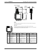
Physical Description
The module, shown below, consists of various components attached to a printed
circuit board. A SMA non-standard female antenna port is located at edge of the
circuit board for attaching a dipole antenna while 24 solder points line the perimeter
of the printed circuit board for the application-specific installation.
Physical View of CWD1014