
User's Manual


Crestron CWD1014 Two-Way RF Transceiver Module
Operations Guide - DOC. 6658 Two-Way RF Transceiver Module: CWD1014 • 3
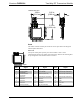
CWD1014 Detail Views
1.00 in
(2.54 cm)
0.35 in
(0.89 cm)
1.54 in
(3.91 cm)
Ports
The module contains 24 solder points and one antenna port. Refer to the diagrams
and descriptions that follow.
Power/I-O
Twenty-four solder points provide power to the module as well as serial
communications between the module and wired devices. Refer to the following table
for pin assignments of the module interface connector.
Power/I-O Pinout Signals
Pin # Signal Pin # Signal Pin # Signal
1
GND 9 Output Amplifier Enable 17 IRQ (active low)
2
Receive Enable
(active low)
10 RX/TX Enable 18 Reserved (No Connection)
3
Transmit Enable
(active low)
11 Attention (active low) 19 Reserved (No Connection)
4
Reserved 12 Reserved (No Connection) 20 Reserved (No Connection)
5
Reserved 13 SPI CLK 21 GND
6
Reserved 14 SPI MOSI 22 GND
7
Reserved 15 SPI MISO 23 VCC 3.3V
8
Reset (active low) 16 SPI_CE (active low) 24 GND