
User Manual


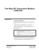
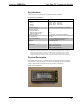
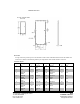
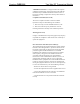

Table Of Contents

Crestron CWD1016 Two-Way RF Transceiver Module
Hardware Guide - DOC. Contents • 3
Specifications
The table below is a summary of specifications for the CWD1016.
Specifications of the CWD1016
SPECIFICATION DETAILS
Power Requirements
Sleep
Receive
Transmit
Typical <5uA Max 11uA
Typical 28mA Max 35mA
Typical 150mA Max 165mA
Operating Frequency 2400 MHz to 2483.5 MHz (802.15.4 compliant)
Operating Ranges¹
Minimum Distance
Maximum Distance Indoors
(without repeater device)
3 ft
150 ft
Available Channels 16 (numbered 11 through 26 per 802.15.4)
RF Output Power 100 mW
Serial Communications TTL Level, 38400 Baud, 8 data bits, 1 stop
bit, no parity, software flow control
Antenna
Board mounted chip
Dimensions Width: 1.88 in (0.477 cm)
Height: 0.82 in (0.208 cm)
Depth: 0.100 in (0.254 cm)
1. The location of the module and the orientation of the antenna are important factors in the RF
performance. The range is dependent on its placement and the building in which it is used. The
construction of the building, obstructions, and RF interference from other devices are factors
determining the effective range of the unit. To prevent unit-to-unit RF interference, multiple
modules operating at the same frequencies should not be installed within 3-5 feet of each other.
Physical Description
The module, shown below, consists of various components attached to a printed
circuit board. A chip antenna port is located at the right edge of the circuit board,
while a 38-pin interface is located on the edges of the circuit board.
Physical View of CWD1016