
User Manual
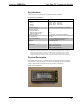
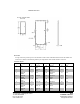
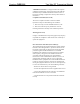
Table Of Contents

Crestron Electronics, Inc. Hardware Guide - DOC. 6351
15 Volvo Drive Rockleigh, NJ 07647 02.28
Tel: 888.CRESTRON INTERNAL USE ONLY
Fax: 201.767.7576 Specifications subject to
www.crestron.com change without notice.
CWD1016 Detail Views
.
Power/I-O
An edge connector provides power to the module as well as serial communications between the module and
wired devices. Refer to the following table for pin assignments of the module interface connector.
/I-O Pinout Signals
Pin # Signal Pin # Signal Pin # Signal Pin # Signal
1 +5v 9 Reserved
GPIO
24 RESET 32 MISO
2 GND 10 Reserved
GPIO
25 Reserved
ADC1
33 GND
3 Reserved
PWMA
11 GND 26 Reserved
ADC2
34 GND
4 Reserved
PWMB
12-16 Reserved
27 Reserved
ADC3
35 PA2
5 Reserved
GPIO
17-20 GND 28 GND 36 GND
6 Reserved
GPIO
21 UART RX 29 Reserved
PA1
62
GND
7 Reserved
GPIO
22 UART TX 30 SCLK
63
+5v
8 Reserved
GPIO
23 Reserved
PA0
31 MOSI