
User Manual


Crestron CWD6660 Two-Way RF Transceiver Module
Operations Guide - DOC. 7028A Two-Way RF Transceiver Module: CWD6660 • 3
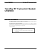
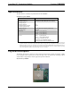
CWD6660 Detail Views
SIDE BACK
t
e
x
t
SE06660
PCB
BACK
RF SHIELD
SMA ANTENNA
16 PIN
HEADER
PCB WITH RADIO
2.0 inch
5.08 cm
1.90 inch
4.83 cm
0.74 inch
1.88 cm
PIN 1
PIN 16
PIN 15
PIN 2
Ports
The module contains a 16-pin header, a 10-pin debug header, and one antenna port.
Refer to the diagrams and descriptions that follow.
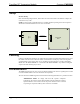
Power/I-O
The 16 pin header provides power to the module as well as communications between the module and
wired devices. Refer to the following table for pin assignments of the module interface connector.
P1
14 12 10 8 6 4 2
16
15 13 11 9 7 5 3 1
(Top View)
NOTE: Pin 1 provides power to the circuit card.
Power/I-O Pinout Signals
Pin # Signal Pin # Signal
1
+5V 2 GND
3
+5V 4 WAKE
5
+3V (NU) 6 LINK_ACTIVITY
7
+3V (NU) 8 HOST_INT
9
SSEL_INT 10 GND
11
SCLK 12 GND
13
MISO 14 MOSI
15
GND 16 RF_RESET_N