
User Manual


Two-Way RF Transceiver Module Crestron CWD6660
4 • Two-Way RF Transceiver Module: CWD6660 Operations Guide - DOC. 7028A
Setup
Hardware Hookup
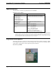
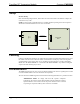
Refer to the hookup diagram below, which shows the connections made to the module. Complete the
connections in any order.
NOTE: To prevent unit-to-unit RF interference, multiple modules operating at the same frequencies
should not be installed within three to five feet of each other.
SE06660
PCB
BACK
PIN 1
PIN 16
PIN 15
PIN 2
HOST PCB
MC3
PIN 1
PI N 16
PI N 15
PIN 2
+5V
CONTROL
Labeling
If the FCC identification number is not visible when the module is installed inside another device, then
the outside of the device into which the module is installed must also display a label referring to the
enclosed module. This exterior label can use wording such as the following: “Contains Transmitter
Module FCC ID: EROCWD6660” or “Contains FCC ID: EROCWD6660.” Any similar wording that
expresses the same meaning may be used.
Documentation
The OEM integrator has to be aware not to provide information to the end user regarding how to install
or remove this RF module in the users manual of the end product.
The users manual for OEM integrators must include the following information in a prominent location
“IMPORTANT NOTE: To comply with FCC RF exposure compliance
requirements, the antenna used for this transmitter must be installed to provide a
separation distance of at least 20 cm from all persons and must not be co-located
or operating in conjunction with any other antenna or transmitter.”