Crestron C2N-FTB FlipTop Control Center with Cresnet® Operations & Installation Guide
This document was prepared and written by the Technical Documentation department at: Crestron Electronics, Inc. 15 Volvo Drive Rockleigh, NJ 07647 1-888-CRESTRON All brand names, product names and trademarks are the property of their respective owners. ©2005 Crestron Electronics, Inc.
FlipTop Control Center with Cresnet® Crestron C2N-FTB Contents FlipTop Control Center with Cresnet®: C2N-FTB 1 Introduction ..........................................................................................................1 Features and Functions...........................................................................1 Specifications .........................................................................................2 Physical Description...................................................
FlipTop Control Center with Cresnet® Crestron C2N-FTB FlipTop Control Center with Cresnet®: C2N-FTB Introduction Features and Functions The C2N-FTB-B and the C2N-FTB-BALUM are Crestron® keypad devices that provide a stylish flush-mount tabletop interface and control solution. The fliptop compartment provides organized storage for a variety of pullout computer, communication, and A/V cables, which stow neatly out of sight within the fliptop compartment when not in use.
FlipTop Control Center with Cresnet® Crestron C2N-FTB C2N-FTB Block Diagram Specifications Specifications for the C2N-FTB are given in the following table. C2N-FTB Specifications SPECIFICATION DETAILS Cresnet Power Usage 2 Watts (0.082 Amp @ 24 VDC) Default Network ID 1E Firmware C2N-FTB.V.1.00.upg or later 2-Series Control System Update Files1,2 Version 3.125.
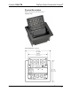
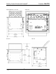
FlipTop Control Center with Cresnet® Crestron C2N-FTB Physical Description Refer to the physical views shown below. Top Open View Physical Dimensions - Top View Operations & Installation Guide – DOC.
FlipTop Control Center with Cresnet® Physical Dimensions - Front View Crestron C2N-FTB Bottom View Back View 4 • FlipTop Control Center with Cresnet®: C2N-FTB Side View Operations & Installation Guide - DOC.
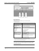
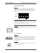
FlipTop Control Center with Cresnet® Crestron C2N-FTB Controls and Ports (Top) Buttons The C2N-FTB can have 10 to 20 engravable, replaceable, programmable buttons. All buttons are functionally identical and have light emitting diodes (LEDs) that serve as user feedback indicators. The illumination of each LED (on/off) is independently addressable, and programmable using SIMPL Windows.
FlipTop Control Center with Cresnet® Crestron C2N-FTB Indicators PWR (Power) This LED illuminates when 24 volts DC is supplied to the C2N-FTB from Cresnet. NET This LED illuminates when communication between the control system and the C2N-FTB is established (the unit is polled on the network). Illumination indicates that the SIMPL Windows program currently loaded has a network device defined at the same Net ID as the C2N-FTB.
FlipTop Control Center with Cresnet® Crestron C2N-FTB CAUTION: Use only Crestron power supplies for Crestron equipment. Failure to do so could cause equipment damage or void the Crestron warranty. NOTE: When installing network wiring, refer to the latest revision of the wiring diagram(s) appropriate for your specific system configuration, available from the Crestron website.
FlipTop Control Center with Cresnet® Crestron C2N-FTB Identity Code Every equipment and user interface within the network requires a unique identity code (Net ID). These codes are two-digit hexadecimal numbers from 03 to FE. The Net ID of each unit must match an ID code specified in the SIMPL Windows program. Refer to “Setting the Net ID in Device Settings” on page 20 for details of the SIMPL Windows procedure Refer to the note on page 23 for a definition of Viewport.
FlipTop Control Center with Cresnet® Crestron C2N-FTB NOTE: The new Net ID code may also be verified by selecting Diagnostic | Report Network Devices in the Viewport (alternately, select F4). 10. Repeat this procedure for each additional network device requiring a Net ID change. Method B (Touch Settable ID) Before using this method, you should have a list of all current network devices and their Net IDs, to avoid assigning duplicate IDs.
FlipTop Control Center with Cresnet® Crestron C2N-FTB CAUTION: This function does not prevent you from setting duplicate IDs. Be sure to check current assignments before entering the desired Cresnet ID number. Serial Number to TSID Conversion This utility is useful in a case where there are multiple devices of the same type on a network, you need to locate a particular one, you know the TSID but not the serial number, and your site installation list is based on device serial numbers.
FlipTop Control Center with Cresnet® Crestron C2N-FTB 1. Remove the four Allen screws that secure the button faceplate. 2. While holding adjacent buttons in place, carefully pull the button(s) to be replaced from the rubber membrane. 3. Carefully press the two small replacement buttons in place, making sure LED window faces up. Use care not to dislodge the membrane and circuit board.
FlipTop Control Center with Cresnet® Crestron C2N-FTB The cable management plate must be installed before mounting the C2N-FTB to a surface. The cables are looped through the cable support plate. A Phillips screwdriver is required to install the cable management plate. 1. Place the bushings on the cables (eight bushings supplied). 2. Thread the cables through the appropriate slot on the plate. 3. Snap the bushings into the plate slots.
FlipTop Control Center with Cresnet® Crestron C2N-FTB Example Cable End Cable Loops Through the Cable Management Plate NOTE: Ensure that the cables have sufficient clearance to enable smooth movement. Allow approximately 40 inches (102 cm) from the top surface of the FlipTop box. Mounting to Surface The C2N-FTB is designed to mount in a horizontal surface, such as a desk top, lectern, or podium. The following diagram illustrates the required opening size to accommodate the C2N-FTB.
FlipTop Control Center with Cresnet® Crestron C2N-FTB Cutout Dimensions 6.375 in (6 3/8 in) (16.19 cm) 5.3125 in (5 5/16 in) (13.494 cm) Maximum Radius 0.125 in (0.318 cm) Mounting Parts Supplied with the C2N-FTB PART DESCRIPTION QUANTITY #6-32, 3/16” Pan Head, Phillips Screw 8 #10-32, 2” Pan Head, Phillips Screw 4 Mounting Bracket 2 A Phillips screwdriver is required to mount the C2N-FTB to a surface.
FlipTop Control Center with Cresnet® Crestron C2N-FTB 3. Install the four #10 screws in the mounting brackets (two screws per bracket). Refer to the following diagram. 4. Slide the mounting brackets over the #6-32 screws and tighten the #6-32 screws using a Phillips screwdriver. 5. Use a Phillips screwdriver to turn the four #10 screws equally until they contact the underside of the mounting surface. NOTE: Do not over-tighten the #10 screws as this may damage the surface and/or the unit.
FlipTop Control Center with Cresnet® Crestron C2N-FTB Consideration must be given if installed in a closed or multi-unit rack assembly, inside a closed desk, or in a closed podium since the operating ambient temperature of these environments may be greater than the room ambient. Contact with thermal insulating materials should be avoided on all sides of the unit.
FlipTop Control Center with Cresnet® Crestron C2N-FTB Configuration Software Have a question or comment about Crestron software? Answers to frequently asked questions (FAQs) can be viewed in the Online Help section of the Crestron website. To post a question or view questions you have submitted to Crestron’s True Blue Support, log in at http://support.crestron.com. First-time users will need to establish a user account. Configuration is easy thanks to Crestron’s Windows-based programming software.
FlipTop Control Center with Cresnet® Crestron C2N-FTB Configuring with Crestron SystemBuilder The Crestron SystemBuilder interface guides you through a few basic steps for specifying the control system, designating rooms and touchpanels, devices, and functionality. The Crestron SystemBuilder then configures the system, including all touchpanel projects and control system logic. It can also connect to Crestron RoomView™ management software.
Crestron C2N-FTB FlipTop Control Center with Cresnet® SIMPL Windows is the Crestron graphical, Windows®-based development tool for programming control systems. The SIMPL Windows interface provides two workspaces: the Configuration Manager, for configuring the control system, touchpanels, and controlled network devices; and Program Manager, for designing the logic and functionality of the control system.
FlipTop Control Center with Cresnet® Crestron C2N-FTB A C2N-FTB in Slot 9 NOTE: The first C2N-FTB in a system is preset with a Net ID of 1E when its symbol is dragged into the upper pane of System Views. Additional units are assigned different Net ID numbers as they are added. Setting the Net ID in Device Settings Double-click the C2N-FTB icon in the upper pane to open the “Device Settings” window. This window displays C2N-FTB device information.
FlipTop Control Center with Cresnet® Crestron C2N-FTB C2N-FTB Symbol in Programming Manager The Buttons module is built into the C2N-FTB. It consists of a 10 to 20 button keypad with LED indicators, and two bargraphs. The button presses are fixed and map to outputs on the symbol detail, as follows: Row 1 Row 2 1 2 3 4 5 6 7 8 9 10 Row 3 Row 4 11 12 13 14 15 16 17 18 19 20 PWR NET NOTE: Numbers in this illustration are for programming purposes only.
FlipTop Control Center with Cresnet® Crestron C2N-FTB C2N-FTB Buttons – Signal Descriptions SIGNAL TYPE AND NAME DESCRIPTION Digital Outputs: Button presses/vertical pair , Button presses/vertical pair , Button presses/vertical pair , Button presses/vertical pair , Button presses/vertical pair , Button presses/vertical pair , Button presses/vertical pair , Button presses/vertical
FlipTop Control Center with Cresnet® Crestron C2N-FTB Uploading and Upgrading NOTE: Crestron recommends that you use the latest software and that each device contains the latest firmware to take advantage of the most recently released features. Please check the Crestron website (http://www.crestron.com/updates) for the latest versions of software and firmware. New users are required to register to obtain access to this site.
FlipTop Control Center with Cresnet® Crestron C2N-FTB The procedure in this section provides details for RS-232 communication between the PC and the control system. If TCP/IP communication is preferred, consult the latest version of the Crestron e-Control Reference Guide (Doc. 6052) or the respective Operations Guide for the control system. These documents are available from the Crestron website. Refer to the following figure for a typical connection diagram when uploading files.
FlipTop Control Center with Cresnet® Crestron C2N-FTB 3. Select RS-232 as the connection type. Verify that an available COM port (COM 1 is shown after this step) is selected, and that all communication parameters and necessary options from the “Port Settings” window are selected as shown after this step. Click the OK button to save the settings and close the window. “Port Settings” Window NOTE: The parameters shown in the illustration above are the port settings for a 2-Series control system. 4.
FlipTop Control Center with Cresnet® Crestron C2N-FTB Upload via Crestron Viewport 1. Verify that the procedure for “Communication Settings” that begins on page 23 has been performed. 2. As shown after this step, select File Transfer | Send Program (alternatively, press Alt+P) from the Viewport menu bar. File Transfer | Send Program Command 3. The “Send Program” window appears, as shown on the next page. Click Browse, locate the compiled file (.spz) and click Open.
FlipTop Control Center with Cresnet® Crestron C2N-FTB Firmware Upgrade A firmware upgrade file has the extension .csf. To take advantage of all the C2N-FTB features, it is important that the unit contains the latest firmware available. Please check the Crestron website for the latest version of firmware. Not every product has a firmware upgrade, but as Crestron improves functions, adds new features, and extends the capabilities of its products, firmware upgrades are posted.
FlipTop Control Center with Cresnet® Crestron C2N-FTB “Select Network ID” Window NOTE: If problems arise when transferring any Cresnet file (touchpanel project/firmware), lower the port speed baud rate to 38400 to match the Cresnet bus speed. “Open” Window 4. Browse to the desired [filename].upg file and click Open to begin the transfer. 28 • FlipTop Control Center with Cresnet®: C2N-FTB Operations & Installation Guide - DOC.
FlipTop Control Center with Cresnet® Crestron C2N-FTB Problem Solving The following table provides corrective action for possible trouble situations. If further assistance is required, please contact a Crestron customer service representative. C2N-FTB Troubleshooting TROUBLE C2N-FTB not functioning. PWR LED does not illuminate. POSSIBLE CAUSE(S) CORRECTIVE ACTION Net ID is not correct. In Viewport, poll the network to verify the Net ID.
FlipTop Control Center with Cresnet® Crestron C2N-FTB Return and Warranty Policies Merchandise Returns / Repair Service 1. No merchandise may be returned for credit, exchange, or service without prior authorization from CRESTRON. To obtain warranty service for CRESTRON products, contact the factory and request an RMA (Return Merchandise Authorization) number. Enclose a note specifying the nature of the problem, name and phone number of contact person, RMA number, and return address. 2.
Crestron C2N-FTB FlipTop Control Center with Cresnet® This page intentionally left blank. Operations & Installation Guide – DOC.
Crestron Electronics, Inc. 15 Volvo Drive Rockleigh, NJ 07647 Tel: 888.CRESTRON Fax: 201.767.7576 www.crestron.com Operations & Installation Guide – DOC. 6338 02.05 Specifications subject to change without notice.