Crestron ABVR-1 Adagio® Balanced Video Receiver Operations Guide
Adagio® Balanced Video Receiver Crestron ABVR-1 Contents Adagio® Balanced Video Receiver: ABVR-1 1 Introduction ............................................................................................................................... 1 Features and Functions ................................................................................................ 1 Applications................................................................................................................. 2 Specifications .
Crestron ABVR-1 Adagio® Balanced Video Receiver ® Adagio Balanced Video Receiver: ABVR-1 Introduction The ABVR-1 is an active balanced-to-unbalanced video converter designed to enable the connection of any Crestron Home® CAT5 balanced video source to a conventional RCA input.
Adagio® Balanced Video Receiver Crestron ABVR-1 Applications The following diagram shows an ABVR-1 and an ABAR-1 in a residential application. ABVR-1 and ABAR-1 in a Residential Application Specifications Specifications for the ABVR-1 are listed in the following table.
Crestron ABVR-1 Adagio® Balanced Video Receiver ABVR-1 Specifications (Continued) SPECIFICATION DETAILS Enclosure Metal with label overlay, freestanding or surface mount with (4) integral mounting flanges Dimensions Height Width Depth Weight * 1.43 in (3.64 cm) 3.91 in (9.94 cm) 4.52 in (11.47 cm) 10 oz (284 g) Actual output signals dependent upon the output capabilities of the CH source device.
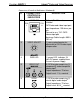
Adagio® Balanced Video Receiver Crestron ABVR-1 ABVR-1 Overall Dimensions 4.52 in (11.47 cm) 3.50 in (8.89 cm) 3.50 in (8.89 cm) 1.43 in (3.64 cm) 3.91 in (9.94 cm) Connectors, Controls & Indicators # CONNECTORS1, CONTROLS & INDICATORS DESCRIPTION 1 24VDC (1) 2-pin 3.5 mm detachable terminal block 24 Volt DC power input (power supply not included) (Continued on following page) 4 • Adagio® Balanced Video Receiver: ABVR-1 Operations Guide – DOC.
Adagio® Balanced Video Receiver Crestron ABVR-1 Connectors, Controls & Indicators (Continued) # CONNECTORS1, CONTROLS & INDICATORS DESCRIPTION 2 VIDEO IN2 (1) 8-pin RJ-45 female, shielded CAT5 balanced video input port Input Impedance: 100 ohms per pair Connect to any “CH” CAT5 video output port Maximum Cable Length: 500 ft (152 m)3 (1) rotary potentiometer for adjustment of CAT5 video input compensation PIN 8 PIN 1 3 VIDEO ADJUST 4 PWR LED 5 VIDEO OUT 6 SPDIF (1) green LED, indicates 24
Adagio® Balanced Video Receiver Crestron ABVR-1 2. This eight-pin RJ-45 port provides connectivity to a device with a CH input port or a Crestron device with a CAT5 video input. This port provides component or composite balanced output over CAT5 wiring. Refer to the following table for connector pinouts.
Crestron ABVR-1 Adagio® Balanced Video Receiver Industry Compliance As of the date of manufacture, the ABVR-1 has been tested and found to comply with specifications for CE marking and standards per EMC and Radiocommunications Compliance Labelling. Federal Communications Commission (FCC) Compliance Statement This device complies with part 15 of the FCC rules.
Adagio® Balanced Video Receiver Crestron ABVR-1 Setup CAT5 Wiring Category 5 (CAT5) wiring is a twisted pair cable designed for Ethernet networks. These networks operate at speeds of up to 100 Megabits per second (Mbps) using the 100BASE-T standard. Crestron takes advantage of this specification for a variety of audio and video applications. Crestron recommends using CresCAT-IM (or D) wire for transmitting video signals from the CH port.
Crestron ABVR-1 Adagio® Balanced Video Receiver Hardware Connections for the ABVR-1 NOTE: For CAT5 connections use Crestron Certified Wire. Operations Guide – DOC.
Adagio® Balanced Video Receiver Fine Tuning Crestron ABVR-1 The output of the ABVR-1 can be adjusted for optimum picture quality using the VIDEO ADJUST control located at the top of the ABVR-1. To adjust the output of the ABVR-1: 1. Connect a video source with a “CH” video output to the VIDEO IN port of the ABVR-1. NOTE: The video source must be able to display the “Streak” test pattern (or similar pattern) shown below. 2.
Adagio® Balanced Video Receiver Crestron ABVR-1 Problem Solving Troubleshooting The following table provides corrective action for possible trouble situations. If further assistance is required, please contact a Crestron customer service representative. ABVR-1 Troubleshooting TROUBLE Device does not function. PWR LED does not illuminate. Poor picture quality. POSSIBLE CAUSE(S) Device is not receiving power from a Crestron power source. Device is not wired correctly.
Adagio® Balanced Video Receiver Crestron ABVR-1 Reference Documents The latest version of all documents mentioned within the guide can be obtained from the Crestron website (www.crestron.com/manuals). This link will provide a list of product manuals arranged in alphabetical order by model number.
Crestron ABVR-1 Adagio® Balanced Video Receiver Return and Warranty Policies Merchandise Returns / Repair Service 1. No merchandise may be returned for credit, exchange or service without prior authorization from CRESTRON. To obtain warranty service for CRESTRON products, contact an authorized CRESTRON dealer. Only authorized CRESTRON dealers may contact the factory and request an RMA (Return Merchandise Authorization) number.
Crestron Electronics, Inc. 15 Volvo Drive Rockleigh, NJ 07647 Tel: 888.CRESTRON Fax: 201.767.7576 www.crestron.com Operations Guide – DOC. 6792A (2023828) 06.09 Specifications subject to change without notice.