Crestron AV2 & PRO2 2-Series Integrated Dual Bus Control System Operations Guide
This document was prepared and written by the Technical Documentation department at: Crestron Electronics, Inc. 15 Volvo Drive Rockleigh, NJ 07647 1-888-CRESTRON All brand names, product names and trademarks are the property of their respective owners. ©2006 Crestron Electronics, Inc.
Crestron AV2 & PRO2 2-Series Integrated Dual Bus Control System Contents 2-Series Integrated Dual Bus Control System: AV2 & PRO2 1 Introduction ............................................................................................................................... 1 Features and Functions ................................................................................................ 1 Specifications .................................................................................................
Crestron AV2 & PRO2 2-Series Integrated Dual Bus Control System 2-Series Integrated Dual Bus Control System: AV2 & PRO2 Introduction Features and Functions • • • • • • • • • • • • 2-Series engine with Dual-bus architecture 36 MB of Internal Memory1 4 GB Compact Flash memory card slot Cresnet port – master/slave selectable 10/100 Ethernet capable with SSL encryption Crestron e-Control2 and Crestron RoomView enabled Built-in firewall, NAT and router Six Com ports, eight IR/serial ports, eight Versiport
2-Series Integrated Dual Bus Control System Crestron AV2 & PRO2 cards (expansion cage option required for AV2). At a blazing 300 Mbps, the Z-Bus supports Fast Ethernet with future support for other emerging technologies. Cresnet® Cresnet is the communications backbone for many Crestron touchpanels, keypads, lighting controls and other devices. The Cresnet bus is a simple, yet flexible 4-wire network that provides rock-solid bidirectional communication and power for up to 252 Cresnet devices.
Crestron AV2 & PRO2 2-Series Integrated Dual Bus Control System Front Panel Control (PRO2 only) The PRO2 includes a programmable front control panel with LCD display and control port status indicators. The PRO2's front panel serves as a ready user interface for system configuration and diagnostics and can also be custom programmed to enable menu-driven control capability. Specifications Specifications for the AV2 & PRO2 are listed in the following table.
2-Series Integrated Dual Bus Control System Crestron AV2 & PRO2 AV2 & PRO2 Specifications (Continued) SPECIFICATION Enclosure DETAILS Black metal, 2U 19” rack-mountable (rack ears included) Dimensions Height 3.47 in (8.82 cm) Width 19.00 in (48.26 cm) with ears; 17.03 in (43.25 cm) without ears Depth 9.69 in (24.61 cm) Weight AV2 7.1 lbs (3.22 kg) – with line cord PRO2 8.0 lbs (3.
Crestron AV2 & PRO2 2-Series Integrated Dual Bus Control System Physical Description This section provides information on the connections, controls and indicators available on your AV2 & PRO2. AV2 Physical View (shown with accessory cards installed in CAGE2; optional) PRO2 Physical View (shown with accessory cards installed) Operations Guide – DOC.
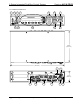
2-Series Integrated Dual Bus Control System Crestron AV2 & PRO2 AV2 & PRO2 Overall Dimensions 1 2 3 8 4 5 9 10 6 7 11 12 9.69 in (24.61 cm) 17.03 in (43.25 cm) 1 13 3.47 in (8.82 cm) 14 15 16 6 • 2-Series Integrated Dual Bus Control System: AV2 & PRO2 17 18 19 Operations Guide – DOC.
Crestron AV2 & PRO2 2-Series Integrated Dual Bus Control System Connectors, Controls & Indicators # CONNECTORS1, CONTROLS & INDICATORS 1 COMPUTER FRONT PANEL DESCRIPTION DB9F connectors (one on front panel and one on rear) are used when programming with a PC. Each port is modem compatible. (Modem and PC cables not included.) REAR PANEL 2 PWR LED Indicates 24 Volts DC power supplied from Cresnet control network. 3 NET LED Indicates communication with Cresnet System.
2-Series Integrated Dual Bus Control System Crestron AV2 & PRO2 Connectors, Controls & Indicators (Continued) # 14 CONNECTORS1, CONTROLS & INDICATORS COM (A – F)5, 6, 7 COM A COM F DESCRIPTION (6) DB9 male, bidirectional RS-232/422/485 ports. Up to 115.2k baud, hardware and software handshaking support. Ports C-F support C2N-NPA8 Network Poll Accelerator8.
Crestron AV2 & PRO2 2-Series Integrated Dual Bus Control System 5. The pinout of each 9-pin port is non-standard; it contains RS-422 pins in addition to RS-232. This may result in a conflict with some equipment and therefore all nine pins should not be used. Only the required pins for each communication type should be connected. For RS-232 and –422, pins 2, 3, 5, 7 and 8 are wired straight through. 6. Data Set Ready (DSR) and Data Terminal Ready (DTR) are not supported. 7.
2-Series Integrated Dual Bus Control System Crestron AV2 & PRO2 Setup Network Wiring When wiring the network, consider the following: • Use Crestron Certified Wire. • Use Crestron power supplies for Crestron equipment. • Provide sufficient power to the system. CAUTION: Insufficient power can lead to unpredictable results or damage to the equipment. Please use the Crestron Power Calculator to help calculate how much power is needed for the system (http://www.crestron.com/calculators).
Crestron AV2 & PRO2 2-Series Integrated Dual Bus Control System ambient temperature of the rack environment may be greater than the room ambient temperature. Contact with thermal insulating materials should be avoided on all sides of the unit. Rack Mounting The AV2 & PRO2 can be mounted in a rack or stacked with other equipment. Two “ears” are provided with the AV2 & PRO2 so that the units can be rack mounted. These ears must be installed prior to mounting.
2-Series Integrated Dual Bus Control System Crestron AV2 & PRO2 bussing strips are constructed with four terminal block positions and may be trimmed to size for various applications or different devices. One strip is supplied for each 8-position terminal block. Memory Card Installation Memory Card Removal 1. To utilize the bussing strip, determine the number of relays to be commoned for the equipment being installed.
Crestron AV2 & PRO2 Connect the Device 2-Series Integrated Dual Bus Control System Make the necessary connections as called out in the illustration that follows this paragraph. Refer to “Network Wiring” on page 10 before attaching the 4-position terminal block connector. Apply power after all connections have been made. When making connections to the AV2 & PRO2, consider the following: • Use Crestron power supplies for Crestron equipment. • The included cable cannot be extended.
2-Series Integrated Dual Bus Control System Crestron AV2 & PRO2 Programming Software Have a question or comment about Crestron software? Answers to frequently asked questions (FAQs) can be viewed in the Online Help section of the Crestron website. To post a question or view questions you have submitted to Crestron’s True Blue Support, log in at http://support.crestron.com. First-time users will need to establish a user account.
Crestron AV2 & PRO2 2-Series Integrated Dual Bus Control System • To incorporate the AV2 or PRO2 into the system, drag the AV2 or PRO2 from the Control Systems folder of the Device Library and drop it in the System Views. Locating the AV2 & PRO2 in the Device Library Programming Manager Programming Manager is the view where programmers “program” a Crestron control system by assigning signals to symbols. The symbol can be viewed by double clicking on the icon or dragging it into Detail View.
2-Series Integrated Dual Bus Control System Crestron AV2 & PRO2 Uploading and Upgrading Crestron recommends using the latest programming software and that each device contains the latest firmware to take advantage of the most recently released features. However, before attempting to upload or upgrade, it is necessary to establish communication.
Crestron AV2 & PRO2 2-Series Integrated Dual Bus Control System • Use the Address Book in the Crestron Toolbox to create an entry for the AV2 or PRO2 with the AV2’s or PRO2’s TCP/IP communication parameters. • Display the “System Info” window (click the or PRO2 entry. • Use the Crestron Toolbox to create the AV2 or PRO2 IP table. icon) and select the AV2 ⇒ Select Functions | IP Table Setup. ⇒ Either add, modify, or delete entries in the IP table. The AV2 or PRO2 can have only one IP table entry.
2-Series Integrated Dual Bus Control System Crestron AV2 & PRO2 Operation Crestron 2-Series Control Systems are the brain of a complete integrated audio/visual or automation solution, serving as the central processor and I/O interface. Every audio, video and environmental element of the home, boardroom, classroom or command center becomes integrated and accessible through the control system.
Crestron AV2 & PRO2 Menu Function Buttons 2-Series Integrated Dual Bus Control System PANEL NOTE: If the unit does not have a loaded program with front panel screens defined, the PANEL menu function does not appear on the Main Menu. This menu function button displays a programmable interface offering command text, indirect text and hierarchical screen structure. For details, refer to the help file in the “Front Panel Editor” utility of SIMPL Windows.
2-Series Integrated Dual Bus Control System Crestron AV2 & PRO2 be too long to be displayed across the top line of the LCD screen; use << and >> to scroll left and right respectively or examine them through Crestron Toolbox. Users may wish to periodically save the error log to a file. This can be an invaluable aid in troubleshooting problems with the control system. Refer to the Crestron Toolbox help file for details.
Crestron AV2 & PRO2 2-Series Integrated Dual Bus Control System “Front Panel Password” Window NOTE: “Front Panel Password” window from Crestron Toolbox version 1.02.29 or later. 5. To change the current password, use the drop down lists to select the four numbers for the new password, then click the Change button. NOTE: New password must be four numbers (each in the range of 1-6).
2-Series Integrated Dual Bus Control System Crestron AV2 & PRO2 Time Set Submenu COM This button allows the user to monitor the transmission and reception traffic on every COM-type device and card that is active in the SIMPL Windows program that is loaded into the 2-Series control system. This includes all devices connected via Cresnet (e.g. ST-COM) and Ethernet (e.g. MC2E or QM-RMC) as well as the builtin card (slot 4) and cards inserted into the expansion slots (e.g. C2COM-2 or C2COM-3).
Crestron AV2 & PRO2 2-Series Integrated Dual Bus Control System Problem Solving Problems may occur with the 2-Series integrated dual bus control system itself or there may be serial communication difficulties with other devices connected to the control system. The next two sections address possible problem solving tools or procedures for each. Possible Problems with the Control System The following table provides corrective action for possible trouble situations.
2-Series Integrated Dual Bus Control System Crestron AV2 & PRO2 AV2 & PRO2 Troubleshooting (Continued) TROUBLE POSSIBLE CAUSE(S) A/V system device does not respond. CORRECTIVE ACTION IRP2 or serial port not placed properly. Verify placement of IRP2 (hold phosphor card under IRP2 while pressing button) and tighten serial cables. Used wrong IR/serial port. Verify that proper IR or serial port is defined. Serial cable not wired correctly.
Crestron AV2 & PRO2 2-Series Integrated Dual Bus Control System top line of the LCD screen provides the COM-type device or card and its port. In the sample shown below, the first active port in the system is the built-in card, port A. The bottom line of the LCD screen provides commands. The user can SELECT the COM port shown on the top line or use NEXT or PREV (appears after scrolling down from the top of the list) to scroll through the entire list of all devices and cards that can be monitored.
2-Series Integrated Dual Bus Control System Crestron AV2 & PRO2 NOTE: Any of the six-menu function buttons toggles the “freeze” state. NOTE: The buffer recycles data even when in the “freeze” state. When the screen is unfrozen, the display jumps to the end of the buffer. T/R Screen with Frozen Sample Check Network Wiring Use the Right Wire In order to ensure optimum performance over the full range of your installation topology, Crestron Certified Wire, and only Crestron Certified Wire, may be used.
Crestron AV2 & PRO2 2-Series Integrated Dual Bus Control System Strip and Tin Wire When daisy-chaining Cresnet units, strip the ends of the wires carefully to avoid nicking the conductors. Twist together the ends of the wires that share a pin on the network connector, and tin the twisted connection. Apply solder only to the ends of the twisted wires. Avoid tinning too far up the wires or the end becomes brittle. Insert the tinned connection into the Cresnet connector and tighten the retaining screw.
2-Series Integrated Dual Bus Control System Crestron AV2 & PRO2 Software License Agreement This License Agreement (“Agreement”) is a legal contract between you (either an individual or a single business entity) and Crestron Electronics, Inc. (“Crestron”) for software referenced in this guide, which includes computer software and, as applicable, associated media, printed materials, and “online” or electronic documentation (the “Software”).
Crestron AV2 & PRO2 2-Series Integrated Dual Bus Control System If You are a business or organization, You agree that upon request from Crestron or its authorized agent, You will within thirty (30) days fully document and certify that use of any and all Software at the time of the request is in conformity with Your valid licenses from Crestron of its authorized agent.
2-Series Integrated Dual Bus Control System Crestron AV2 & PRO2 Return and Warranty Policies Merchandise Returns / Repair Service 1. No merchandise may be returned for credit, exchange, or service without prior authorization from CRESTRON. To obtain warranty service for CRESTRON products, contact an authorized CRESTRON dealer. Only authorized CRESTRON dealers may contact the factory and request an RMA (Return Merchandise Authorization) number.
Crestron AV2 & PRO2 2-Series Integrated Dual Bus Control System This page is intentionally left blank. Operations Guide – DOC.
Crestron Electronics, Inc. 15 Volvo Drive Rockleigh, NJ 07647 Tel: 888.CRESTRON Fax: 201.767.7576 www.crestron.com Operations Guide – DOC. 5957B (2002056) 06.06 Specifications subject to change without notice.