
User Guide


Crestron BB-1700CW Wall Mount Back Box for STX-1700CW
NOTE: To be properly installed, the cutout area of the gypsum board must be cut to
within 1/8-inch (0.32 cm) of the outline of the back box enclosure.
NOTE: The next step is performed after the gypsum board is hung. The only tools
required are a ruler and a #2 Phillips screwdriver.
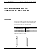
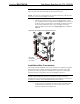
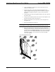
7. After the gypsum board is hung, refer to the diagram below. Using a
ruler, adjust the back box to approximately 1/16-inch (0.15 cm) inward
of the face of the gypsum board to accommodate the distance between
the back box and the front panel. Using a #2 Phillips screwdriver,
tighten the four pair of bracket screws finger-tight plus an additional
1/8-turn.
Adjust Back Box Clearance and Tighten Bracket Screws
BACK BOX
CLEARANCE
(ALL SIDES)
Installation After Construction
This section describes installation when room construction is complete and gypsum
board has been hung. Complete the following installation procedure in the order
provided. The only tools required are a stud finder (or equivalent), masking tape,
gypsum board saw (or equivalent), ruler and a #2 Phillips screwdriver.
NOTE: This procedure installs the left-side of the back box to the right-side of a
framing stud. If installing the back box to the left-side of a stud, reverse the
mounting bracket and the mounting support bracket but maintain the orientation of
the back box enclosure with the manual unlatching notch at the top.
1. Locate an area on the wall that the back box (and touchpanel) will be
installed. Make sure that the area is clear of studs, wires, or other
obstructions within the installation area.
Installation Guide – DOC. 6105 Wall Mount Back Box for STX-1700CW: BB-1700CW • 5