Crestron BB-4L Wall Mount Back Box Installation Guide
This document was prepared and written by the Technical Documentation department at: Crestron Electronics, Inc. 15 Volvo Drive Rockleigh, NJ 07647 1-888-CRESTRON All brand names, product names and trademarks are the property of their respective owners. ©2005 Crestron Electronics, Inc.
Crestron BB-4L Wall Mount Back Box Contents Wall Mount Back Box: BB-4L 1 Description................................................................................................................................. 1 Installation ................................................................................................................................. 3 Assembly ..................................................................................................................... 3 Mounting .........
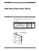
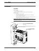
Crestron BB-4L Wall Mount Back Box Wall Mount Back Box: BB-4L Description The BB-4L is a UL®-listed pre-construction mounting option for the Crestron Isys® TPS-4L and TPMC-4L wall mounted touchpanels. The table below lists all parts included with the BB-4L.
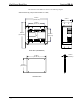
Wall Mount Back Box Crestron BB-4L The dimensions of the BB-4L are shown in the following diagram. Dimensional Drawing (Fully Assembled without Cover Plate) 6.93 in (17.60 cm) 3.31 in (8.41 cm) 5.00 in (12.70 cm) 8.27 in (21.01 cm) 3.90 in (9.91 cm) BACK BOX (ASSEMBLED) 6.00 in (15.24 cm) 0.03 in (0.08 cm) 4.50 in (11.43 cm) COVER PLATE 2 • Wall Mount Back Box: BB-4L Installation Guide - DOC.
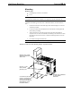
Crestron BB-4L Wall Mount Back Box Installation Assembly Required Tools: • #2 Phillips tip screwdriver Complete the following assembly procedure in the order provided (refer to illustration below). 1. Remove knockouts as required. 2. Attach the supplied #08-8B self-tapping screw to back box mounting enclosure assembly for grounding. 3. Attach upper and lower mounting brackets to back box mounting enclosure assembly using supplied (4) #6-32 x 1/4” screws.
Wall Mount Back Box Crestron BB-4L Mounting Required Tools: • #2 Phillips tip screwdriver or hammer • Level NOTE: If your installation is not on wooden studs, be sure to consider the needs of your particular situation. For example, screw type may vary for steel studs, etc. Complete the following procedure (refer to illustration below) to mount the back box. 1. Position the back box at the front edge of the stud and align it as even and as flush as possible. 2.
Crestron BB-4L Wall Mount Back Box CAUTION: Allow an air gap of at least 12 inches in the wall cavity above and below the touchpanel for heat dissipation. NOTE: A pair of cutout templates is provided with the touchpanel to be installed. The templates allow you to cut either around the outside or around the inside. Choose whichever is more convenient for your situation. 5.
Wall Mount Back Box Crestron BB-4L Future Updates As Crestron adds improvements to the BB-4L, additional information may be made available as manual updates. These updates are solely electronic and serve as intermediary supplements prior to the release of a complete technical documentation revision. Check the Crestron website periodically for manual update availability and its relevance. Updates are identified as an “Addendum” in the Download column.
Crestron BB-4L Wall Mount Back Box Return and Warranty Policies Merchandise Returns / Repair Service 1. No merchandise may be returned for credit, exchange, or service without prior authorization from CRESTRON. To obtain warranty service for CRESTRON products, contact the factory and request an RMA (Return Merchandise Authorization) number. Enclose a note specifying the nature of the problem, name and phone number of contact person, RMA number, and return address. 2.
Crestron Electronics, Inc. 15 Volvo Drive Rockleigh, NJ 07647 Tel: 888.CRESTRON Fax: 201.767.7576 www.crestron.com Installation Guide – DOC. 6387 (2013259) 12.05 Specifications subject to change without notice.