Crestron C2N-DB6/8/12 Decorator Wall Panels Operations & Installation Guide
This document was prepared and written by the Technical Documentation department at: Crestron Electronics, Inc. 15 Volvo Drive Rockleigh, NJ 07647 1-888-CRESTRON All brand names, product names and trademarks are the property of their respective owners. ©2003 Crestron Electronics, Inc.
Crestron C2N-DB6/8/12 Decorator Wall Panels Contents Decorator Wall Panels: C2N-DB6/8/12 .............................. 1 Introduction......................................................................................1 Features and Functions ..........................................................1 Specifications.........................................................................3 Physical Description ..............................................................4 Button Replacement ............
Crestron C2N-DB6/8/12 Decorator Wall Panels Decorator Wall Panels: C2N-DB6/8/12 Introduction Features and Functions The C2N-DB6/8/12-series Decorator Wall Panels are wall-mounted, single-gang user interfaces that can be part of a Crestron® solution total control system. The panels are standard Cresnet® devices, and provide fingertip control when the control system is properly programmed using Crestron’s SIMPL Windows, Application Builder, or D3 Pro software.
Decorator Wall Panels Crestron C2N-DB6/8/12 Faceplates are not supplied; the wall panels accept faceplates that can be obtained in any store selling lighting supplies and accessories, making it easy for the wall panels to match the appearance of the site’s other switch and outlet styles. NOTE: The C2N-DB12 wall panel is supplied with 12 blank pushbuttons. As an option, custom-engraved keys can be designed and obtained by using the Crestron Engraver software. Version 2.1.0.
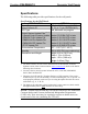
Crestron C2N-DB6/8/12 Decorator Wall Panels Specifications The following table provides specifications for the wall panels. Specifications for the Wall Panels SPECIFICATION Power Requirements Default Network ID LED Type Control System Update Files1, 2, 3 2-Series Control System Update CEN/CN-TVAV Update File CNMSX-AV/Pro Update File CNRACKX/-DP Update File ST-CP Update File Environmental Temperature Humidity Dimensions and Weight DETAILS 3 Watts (0.
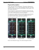
Decorator Wall Panels Crestron C2N-DB6/8/12 Physical Description Refer to the figures below and on page 5. The number of buttons on a wall panel can be 6, 8, or 12. They are arranged numerically from left to right, top to bottom and each has an LED window. (Refer to page 19 for join number information.) Each wall panel has a button unit with a membrane switch, and a male Cresnet network port labeled 24 Y Z G. The port provides for operating power and for communications to/from the wall panel.
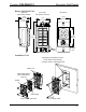
Crestron C2N-DB6/8/12 Decorator Wall Panels Button Unit Detail View Back View Front View with buttons removed Side View with buttons installed 1.53 in (3.89 cm) 1.67 in (4.24 cm) 1.79 in (4.55 cm) 1.07 in (2.72 cm) 4.16 in (10.57 cm) 2.70 in (6.86 cm) Rubber Membrane Cresnet port Installation View Single gang electrical box shown; (2.5 in. depth recommended) Can also mount in multi-gang boxes Button unit Removable buttons (See CAUTION on page 6.) Divider LED window 2-28 x 3/16 in.
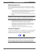
Decorator Wall Panels Crestron C2N-DB6/8/12 Button Replacement Replacing/changing the removable buttons in a Wall Panel is a simple process. Refer to the illustrations on the previous page and the following procedures. 1. If the wall panel is installed in an electrical box, remove the two 1-inch securing screws, carefully pull the wall panel from the electrical box, and disconnect the Cresnet cable. 2. Remove the four screws that attach the divider, and remove the divider.
Crestron C2N-DB6/8/12 Decorator Wall Panels Setup Network Wiring CAUTION: Use only Crestron power supplies for Crestron equipment. Failure to do so could cause equipment damage or void the Crestron warranty. NOTE: When installing network wiring, refer to the latest revision of the wiring diagram(s) appropriate for your specific system configuration, available from the Downloads | Product Manuals | Wiring Diagrams section of the Crestron website (www.crestron.com). NOTE: For larger networks (i.e.
Decorator Wall Panels Crestron C2N-DB6/8/12 Wire Gauge Values RESISTANCE (R) WIRE GAUGE 4 16 6 18 10 20 15 22 13 Doubled CAT5 8.7 Tripled CAT5 NOTE: All Cresnet wiring must consist of two twisted pairs. One twisted pair is the +24V conductor and the GND conductor, and the other twisted pair is the Y conductor and the Z conductor. NOTE: When daisy-chaining Cresnet units, strip the ends of the wires carefully to avoid nicking the conductors.
Crestron C2N-DB6/8/12 Decorator Wall Panels “Troubleshooting Communications” section in the respective Operations Guide for the control system. There are two different methods—Method A or Method B—for setting the wall panel NET IDs: Method A (Cresnet address-settable ID), described below, applies to all wall panels in a Cresnet system. This method requires that a single wall panel be the only network device connected to the control system.
Decorator Wall Panels Crestron C2N-DB6/8/12 NOTE: The new NET ID code may also be verified by selecting Diagnostics | Report Network Devices in the Viewport (alternately, select F4). 10. Repeat this procedure for each wall panel to be added to the system. Method B (Touch Settable IDs) Before using this method, you should have a list of all current network devices and their Net IDs, to avoid assigning duplicate IDs. Set Net ID via D3 Pro Version 1.
Crestron C2N-DB6/8/12 Decorator Wall Panels “Set Net ID by TSID” Window 4. As you enter either the serial number or TSID number of the device that requires a change, the corresponding TSID or serial number automatically appears in its appropriate field, and the list scrolls to and highlights the device listing. The listing should show the device’s current Cresnet ID. CAUTION: This function does not prevent you from setting duplicate IDs.
Decorator Wall Panels 2. Crestron C2N-DB6/8/12 From the Viewport menu, select Functions | Serial Number ÅÆ TSID Conversion Tool. The “Serial Number ÅÆTSID Conversion Tool” window is displayed. “Serial Number to TSID Conversion Tool” Window 3. Enter the serial number or TSID number as instructed; press the appropriate button to obtain the corresponding number. NOTE: Enter serial numbers, including spaces, exactly as they appear on the unit label.
Crestron C2N-DB6/8/12 2. Decorator Wall Panels Connect the Cresnet cable with supplied mate to the wall panel’s Cresnet port and the other end to the control system. CAUTION: Excess wire pinched between the wall panel and electrical box could short out. Make sure that all excess wire is completely inside the electrical box and not between the box and the side of the wall panel. 3. Make sure the button unit is oriented as marked with arrow at top, and place it in the electrical box. 4.
Decorator Wall Panels Crestron C2N-DB6/8/12 different look-and-feel, this can be accomplished by making a custom template. This custom template can then be used by Crestron AppBuilder to create the final project files to be loaded into the panels. Alternatively, VT Pro-e can be used to tweak projects created with the Crestron AppBuilder or develop original touchpanel screen designs. NOTE: Crestron recommends that you use the latest software to take advantage of the most recently released features.
Crestron C2N-DB6/8/12 Decorator Wall Panels Programming with SIMPL Windows NOTE: The following assumes that the reader has knowledge of SIMPL Windows. If not, refer to the extensive help information provided with the software. NOTE: In the following description, the PRO2 control system is used. SIMPL Windows is Crestron's software for programming Crestron control systems. It provides a well-designed graphical environment with a number of workspaces (i.e.
Decorator Wall Panels Crestron C2N-DB6/8/12 Expanded PRO2 System Tree C2Net-Device Slot in Configuration Manager To incorporate a C2N-DB12 into the system, drag the C2N-DB12 from the Wired Keypad folder of the Device Library and drop it in System Views. The PRO2 system tree displays the C2N-DB12 in Slot 9, with a default NET ID of 71 as shown in the illustration on the next page.
Crestron C2N-DB6/8/12 Decorator Wall Panels Setting the Net ID in Device Settings Double-click the C2N-DB12 icon in the upper pane to open the “Device Settings” window. This window displays C2N-DB12 device information. The NET ID can be changed in this window using the NET ID tab, as shown in the following figure. “C2N-DB12 Device Settings” Window NOTE: This procedure sets the NET ID for the C2N-DB12 in the program only. It does not automatically set the NET ID for the wall panel itself.
Decorator Wall Panels Crestron C2N-DB6/8/12 C2N-DB12 symbol in SIMPL Windows Programming Manager NOTE: In the symbol, the number of press and fbck (feedback)—outputs and inputs, respectively—correspond to the number of buttons in a given wall panel. For example, a C2N-DB8 has only press1-8 and fbck1-8 in its symbol in addition to the LED brightness control (IndicatorIntensity). Refer to the button arrangement illustration on the next page.
Crestron C2N-DB6/8/12 Decorator Wall Panels Button Arrangement of C2N-DB Series Wall panels (Front Views) press 1 press 3 press 5 press 2 press 1 press 4 press 3 press 1 press 2 press 3 press 4 press 5 press 6 press 7 press 8 press 2 press 4 press 5 press 6 press 9 press 10 press 7 press 8 press 11 press 12 press 6 The following table lists the symbol input and output signals, respectively, and their functional descriptions.
Decorator Wall Panels Crestron C2N-DB6/8/12 Example Program An example program for the wall panel is available from the Crestron FTP site (ftp://ftp.crestron.com/Examples). Search for C2N-DB12.ZIP. Uploading and Upgrading Assuming a PC is properly connected to the entire system, Crestron programming software allows the programmer to upload programs and projects to the system and touchpanel and firmware to the wall panels after their development.
Crestron C2N-DB6/8/12 Decorator Wall Panels serial adapters. If a USB-to-serial adapter must be used, Crestron has tested the following devices with good results: Belkin (large model) F5U103 I/O Gear GUC232A Keyspan USA-19QW Other models, even from the same manufacturer, may not yield the same results. The procedure in this section provides details for RS-232 communication between the PC and the control system.
Decorator Wall Panels Crestron C2N-DB6/8/12 1. Open the Crestron Viewport. Either launch the stand-alone version of Viewport, or start SIMPL Windows and from the menu bar, select Tools | Viewport. 2. Refer to the figure after this step. From the Viewport menu, select Setup | Communications settings (alternatively, press Alt+D) to open the “Port Settings” window. Setup | Communications Settings Command 3. Select RS-232 as the connection type.
Crestron C2N-DB6/8/12 Decorator Wall Panels “Port Settings” Window NOTE: The parameters shown in the illustration above are the port settings for a 2-Series control system. Consult the Operations Guide for the control system being used for exact parameter selection. 4. To verify communication, select Diagnostics | Establish Communications (Find Rack). This should display a window that gives the COM port and baud rate.
Decorator Wall Panels Crestron C2N-DB6/8/12 Uploading a SIMPL Windows Program A control system source file has the extension .smw. A compiled SIMPL Windows file has the extension .spz for a 2-Series control system, .bin for CNX generation, and .csz for CNX generation with SIMPL+. The SIMPL Windows file can be uploaded to the control system using SIMPL Windows or via the Crestron Viewport. Upload via SIMPL Windows 1. Start SIMPL Windows. 2.
Crestron C2N-DB6/8/12 Decorator Wall Panels “Send Program” Window 4. To verify that the program has been transferred successfully, select Diagnostics | Report Program Information. This should display a window that provides details about the current program loaded into the control system. Firmware Upgrade A firmware upgrade file has the extension .csf. To take advantage of all the C2N-DB12 features, it is important that the unit contains the latest firmware available.
Decorator Wall Panels Crestron C2N-DB6/8/12 File Transfer | Update Touchpanel/Keypad Firmware Command 3. As shown in the “Select Network ID” window, select the NET ID of the C2N-DB12, and then click OK. The “Open” window appears (refer to the graphics below and on the next page). “Select Network ID” Window NOTE: When transferring a Cresnet file (touchpanel project/ firmware), lower the port speed baud rate to 38400 to match the Cresnet bus speed.
Crestron C2N-DB6/8/12 Decorator Wall Panels “Open” Window NOTE: Firmware upgrades to the button panel include two files, [filename]a.csf and [filename]b.csf. Select the ‘a’ file to begin the upload; the ‘b’ file is loaded automatically. 4. Browse to the desired [filename]a.csf file and click Open to begin the transfer. The program automatically sends the ‘a’ file and then the ‘b’ file.
Decorator Wall Panels Crestron C2N-DB6/8/12 “Serial Number Assignment” Window 3. Enter the device serial number exactly as it appears on the device label. 4. Use the drop-down list to change the current Cresnet ID. NOTE: Do not select the Broadcast check box unless your wall panel is the only one of its type on the network. 5. Click Send to store the serial number and NET ID information into the wall panel’s memory. 28 • Decorator Wall Panels: C2N-DB6/8/12 Operations & Installation Guide - DOC.
Crestron C2N-DB6/8/12 Decorator Wall Panels Problem Solving Troubleshooting The table below provides corrective action for possible trouble situations. If further assistance is required, please contact a Crestron customer service representative. Wall Panel Troubleshooting TROUBLE POSSIBLE CAUSE(S) Wall panel does not function when a button is pressed. Incorrect power supply. Wall panel is not receiving power. Wall panel Net ID is not correct.
Decorator Wall Panels Crestron C2N-DB6/8/12 Further Inquiries If, after reviewing this Operations and Installation Guide for the wall panels, you cannot locate specific information or have questions, please take advantage of Crestron's award winning customer service team in your area. Dial one of the following numbers. • In the US and Canada, call Crestron's corporate headquarters at 1-888-CRESTRON [1-888-273-7876]. • In Europe, call Crestron International at +32-15-50-99-50.
Crestron C2N-DB6/8/12 Decorator Wall Panels Return and Warranty Policies Merchandise Returns / Repair Service 1. No merchandise may be returned for credit, exchange, or service without prior authorization from CRESTRON. To obtain warranty service for CRESTRON products, contact the factory and request an RMA (Return Merchandise Authorization) number. Enclose a note specifying the nature of the problem, name and phone number of contact person, RMA number, and return address. 2.
Crestron Electronics, Inc. 15 Volvo Drive Rockleigh, NJ 07647 Tel: 888.CRESTRON Fax: 201.767.7576 www.crestron.com Operations & Installation Guide - DOC. 6154 06.03 Specifications subject to change without notice.