
User Guide

Crestron C2N-DB6/8/12 Decorator Wall Panels
Operations & Installation Guide - DOC. 6154 Decorator Wall Panels: C2N-DB6/8/12 • 19
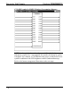
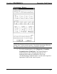
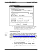
Button Arrangement of C2N-DB Series Wall panels (Front Views)
press 1
press 2
press 3
press 4
press 5
press 6
press 1
press 2
press 3
press 4
press 5
press 6
press 7
press 8
press 1
press 2
press 3
press 4
press 5
press 6
press 7
press 8
press 9
press 10
press 11
press 12
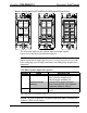
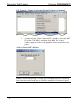
The following table lists the symbol input and output signals,
respectively, and their functional descriptions.
NOTE: All signals listed in the table are DIGITAL unless noted. A
digital signal can be high (logic level of 1) or low (logic level of 0), and
have rising edge (low to high) transitions, and falling edge (high to low)
transitions.
C2N-DB12 Symbol Signal Descriptions
SIGNAL NAME DESCRIPTION
Input fbck1 thru fbck12 Activates feedback LEDs 1-12.
High/1=function feedback On
Low/0=function feedback Off
IndicatorIntensity Controls LED indicator intensity.*
(analog) Ramp Level=0-100% (If no signal is
connected, default is 100%.)
Output press1 thru press12 Notifies control system of button press
(1-12).
*Sets LED value for all feedback indicators.
NOTE: The join assignments for panels with fewer than 12 buttons and
feedback LEDs do not change.