Crestron C2N-FT-TPS4/TPS4-U FlipTop Touchpanel Control Center Operations & Installation Guide
This document was prepared and written by the Technical Documentation department at: Crestron Electronics, Inc. 15 Volvo Drive Rockleigh, NJ 07647 1-888-CRESTRON All brand names, product names and trademarks are the property of their respective owners. ©2005 Crestron Electronics, Inc.
Crestron C2N-FT-TPS4/TPS4-U FlipTop Control Center Contents FlipTop Touchpanel Control Center: C2N-FT-TPS4/TPS4-U 1 Introduction ..........................................................................................................1 Features and Functions...........................................................................1 Specifications .........................................................................................2 Physical Description..............................................
Crestron C2N-FT-TPS4/TPS4-U FlipTop Control Center FlipTop Touchpanel Control Center: C2N-FT-TPS4/TPS4-U Introduction Features and Functions The C2N-FT-TPS4 and C2N-FT-TPS4-U FlipTop Touchpanel control centers (TPS4) comprise a touchpanel housed in a flip top mechanical enclosure. The only difference between the units is that the TPS4-U (universal) does not contain an AC power outlet. All references to TPS4 apply to both units unless specified otherwise. The TPS4 touchpanel is a compact Crestron 3.
FlipTop Touchpanel Control Center Crestron C2N-FT-TPS4/TPS4-U graphics, the TPS4 produces astounding 3D graphics, dynamic text, and full-motion animations complete with WAV file audio feedback. Ten programmable pushbuttons are also included featuring translucent buttons with white LED backlighting and an engravable faceplate. The units support both Cresnet and Ethernet protocols for communication with other devices as well as uploading programs and firmware.
Crestron C2N-FT-TPS4/TPS4-U FlipTop Touchpanel Control Center C2N-FT-TPS4/TPS4-U Specifications (continued) SPECIFICATION DETAILS Touchpanel Processor CPU Processing Speed 32-bit Freescale Coldfire Microprocessor 96 MIPS Touchpanel Memory 8MB internal flash; 16MB DRAM Touchpanel Ethernet Support 10/100Base-T Full duplex, Link and Activity LEDs Operating Temperature and Humidity 41º to 104º F (5º to 40º C) 10 to 90% relative humidity (non-condensing) Dimensions and Weight Width: 7.67 in (19.
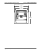
FlipTop Touchpanel Control Center Crestron C2N-FT-TPS4/TPS4-U TPS4 Physical Dimensions – Top View 7.67 in (19.49 cm) 6.00 in (15.24 cm) CONTROL CENTER 6.55 in (16.64 cm) 4 • FlipTop Touchpanel Control Center: C2N-FT-TPS4/TPS4-U Operations & Installation Guide - DOC.
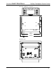
Crestron C2N-FT-TPS4/TPS4-U FlipTop Touchpanel Control Center TPS-4 Physical Dimensions - Front View 6.28 in (15.96 cm) 7.17 in (18.22 cm) TPS4 Bottom View LAN Operations & Installation Guide – DOC.
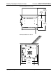
FlipTop Touchpanel Control Center Crestron C2N-FT-TPS4/TPS4-U TPS4 Physical Dimensions - Back View 2.75 in (6.99 cm) 0.09 in (0.23 cm) 4.66 in (11.84 cm) 5.67 in (14.40 cm) TPS4 Physical Dimensions - Side View 5.51 in (14.0 cm) 6.05 in (15.37 cm) 6 • FlipTop Touchpanel Control Center: C2N-FT-TPS4/TPS4-U Operations & Installation Guide - DOC.
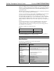
Crestron C2N-FT-TPS4/TPS4-U FlipTop Touchpanel Control Center Controls and Ports (Top) Buttons The TPS-4 touchpanel has 10 hard buttons; five on each side of the display. The buttons are backlit with white LEDs; brightness is program adjustable. The buttons can be programmed to automate frequently used functions. 125V – 50/60Hz 10A AC Outlet (C2N-FT-TPS4 Only) The 3-prong grounded AC outlet is rated 125 VAC @ 10 Amps, 50 – 60 Hz.
FlipTop Touchpanel Control Center Crestron C2N-FT-TPS4/TPS4-U Setup Network Wiring CAUTION: In order to ensure optimum performance over the full range of your installation topology, Crestron Certified Wire, and only Crestron Certified Wire, may be used. Failure to do so may incur additional charges if support is required to identify performance deficiencies as a result of using improper wire. CAUTION: Use only Crestron power supplies for Crestron equipment.
Crestron C2N-FT-TPS4/TPS4-U FlipTop Touchpanel Control Center Crestron Toolbox The Crestron Toolbox (replacement for Crestron Viewport) is a broad-based software package that accomplishes multiple system tasks, primarily using an RS-232 or TCP/IP connection between a PC and one or more Crestron control systems. You can use the Crestron Toolbox to: • Observe system processes. • Upload operating systems and firmware. • Upload programs and touchpanel projects. • Set or change device Network IDs.
FlipTop Touchpanel Control Center Crestron C2N-FT-TPS4/TPS4-U Duplicate Net ID Warning Message This method does not change the Net ID as assigned in SIMPL windows. Refer to page 20 for the SIMPL Windows ID change procedure. NOTE: You may also use SystemBuilder to perform Network ID setup. 1. Ensure that all network devices are connected to the control system. 2. Open Crestron Toolbox and establish communications (refer to page 22). 3.
Crestron C2N-FT-TPS4/TPS4-U FlipTop Touchpanel Control Center 6. An alert message appears to notify you that the change was successful. 7. Repeat this procedure for each network device requiring a Net ID change. Installation Physical installation of the TPS4 includes installing an engraved touchpanel bezel, installation of the supplied cable management plate, and mounting the unit to the desired surface.
FlipTop Touchpanel Control Center Crestron C2N-FT-TPS4/TPS4-U Parts Supplied for the Optional Cable Management Plate PART DESCRIPTION QUANTITY Small Cable Bushing, 5/16 inch ID, 0.5 inch OD 4 Medium Cable Bushing, 0.39 inch ID, 0.64 inch OD 2 Large cable Bushing, 0.55 inch ID, 0.80 inch OD 2 Cable Support Plate 1 Screws, 4-40 x ¼ , black, Phillips head 4 The only tool required for installation of the cable support plate is a Phillips screwdriver.
Crestron C2N-FT-TPS4/TPS4-U FlipTop Touchpanel Control Center Cutout Dimensions TPS4 (4007478) 7.25 in (18.42 cm) 6.13 in (15.56 cm) Max Radius (0.125 in) (0.32 cm) NOTE: Before inserting the TPS4 in the mounting hole, ensure that all required cables have been installed. Mounting Parts Supplied with the TPS4 PART DESCRIPTION Screw #6-32, Pan Head, Phillips QUANTITY 8 Screw #10, Pan Head, Phillips 4 Mounting Bracket 2 1.
FlipTop Touchpanel Control Center 5. Crestron C2N-FT-TPS4/TPS4-U Turn the four #10 screws equally until they contact the underside of the mounting surface. NOTE: Do not over-tighten the #10 screws as this may damage the surface and/or the unit. Mounting Bracket Installation NOTE: Be careful not to press any screen pushbuttons or hard keys while closing the Flip Top, even though the screen is disabled when the Flip Top begins to close and all pressed buttons are released.
Crestron C2N-FT-TPS4/TPS4-U FlipTop Touchpanel Control Center Underside Connections GROUND LAN 120 VAC LINE CORD (C2N-FT-TPS4 ONLY) CRESNET: TO CONTROL SYSTEM AND OTHER CRESNET DEVICES ETHERNET: 10/100 BASE-T ETHERNET TO LAN Configuring the Touchpanel NOTE: The only connection required to configure the touchpanel is power. Refer to “Hardware Hookup” on page 14 for details. MAIN MENU NOTE: The touch screen responds to both finger and stylus commands.
FlipTop Touchpanel Control Center Crestron C2N-FT-TPS4/TPS4-U NOTE: When touching each crosshair during calibration, be as accurate as possible. Use a stylus or the tip of a capped pen or the eraser end of a pencil. To cancel calibration and return to the CALIBRATION MENU without saving calibration data, create a calibration error by touching the screen in an area that is opposite from the instructed area.
Crestron C2N-FT-TPS4/TPS4-U FlipTop Touchpanel Control Center Press the Restore Default Audio Settings button to cancel any changes and restore all default audio settings: WAV volume = 100%, and WAV function enabled; key click volume = 100%, and key click function enabled. Press Return to save the settings and return to the SETUP MENU. Screen Settings SCREEN SETTINGS From the SETUP MENU, press the Screen Settings button to open the SCREEN SETTINGS screen, shown at left.
FlipTop Touchpanel Control Center Crestron C2N-FT-TPS4/TPS4-U submitted to Crestron’s True Blue Support, log in at http://support.crestron.com. First-time users will need to establish a user account. You can create a program that allows you to include the TPS4 in a Crestron control system. The program output of Crestron SystemBuilder is a SIMPL Windows program with much of the functionality encapsulated in macros and templates. Therefore, extending the capabilities of the system is very easy.
Crestron C2N-FT-TPS4/TPS4-U FlipTop Touchpanel Control Center Programming with SystemBuilder The easiest method of programming, but does not offer as much flexibility as SIMPL Windows. Crestron SystemBuilder offers automatic programming for such residential and commercial applications as audio distribution, home theater, video conferencing, and lighting.
FlipTop Touchpanel Control Center Crestron C2N-FT-TPS4/TPS4-U System View of PRO2 The System Views lower pane displays the PRO2 system tree. This tree can be expanded to display and configure the communications ports. Expanded PRO2 System Tree C2Net-Device Slot in Configuration Manager To incorporate a TPS4 into the system, drag the C2N-FT-TPS-4 (Cresnet) from the Touchpanels | Touchpanels (Cresnet) folder of the Device Library and drop it in System Views.
Crestron C2N-FT-TPS4/TPS4-U FlipTop Touchpanel Control Center “Device Settings” Window NOTE: This procedure sets the Net ID for the TPS4 in the program only. It does not automatically set the Net ID for the C2N-FT-TPS4/TPS4-U hardware. SIMPL Windows automatically changes Net ID values of a device added to a program if a duplicate device or a device with the same Net ID already exists in the program. Always ensure that the hardware and software settings of the Net ID match.
FlipTop Touchpanel Control Center Crestron C2N-FT-TPS4/TPS4-U programmed project until another set is uploaded from the PC. The PC may be disconnected from the control system or panel except during reprogramming. When you start the VT Pro-e project for this product, select C2N-FT-TPS4 as the panel type. For additional software information, refer to the help file provided with the software. The latest version of VT Pro-e can be obtained from the Crestron website.
Crestron C2N-FT-TPS4/TPS4-U FlipTop Touchpanel Control Center Typical Connection Diagram when Uploading NOTE: Use a straight-through serial cable for connection to a 2-Series processor. 1. Open Crestron Toolbox and click Tools | Manage Address Book to display the communications settings. The DefaultAddressBook.adr file contains several default address settings. Select Serial on COM 1 for serial communication.
FlipTop Touchpanel Control Center Crestron C2N-FT-TPS4/TPS4-U 2. After setting the correct parameters, click OK to return to the Crestron Toolbox main window. 3. Select Tools | System Info. If the connection is successful, the System Info window displays the processor and device information. System Info Window NOTE: To enter the console mode, click the console mode icon . Uploading a SIMPL Windows Program A control system source file has the extension .smw.
Crestron C2N-FT-TPS4/TPS4-U FlipTop Touchpanel Control Center 2. Once communication is established, the Functions menu becomes available. 3. Select Functions | SIMPL Program…The “SIMPL Program” window appears, as shown in the following figure, and permits you to browse for a compiled program file (.spz), and to upload it to internal flash. “SIMPL Program” Window 4. Browse for the appropriate .spz file in the “Open” window, and click Open. “Open” Window 5.
FlipTop Touchpanel Control Center Crestron C2N-FT-TPS4/TPS4-U Firmware Upgrade To take advantage of all the C2N-FT-TPS4/TPS4-U features, it is important that the unit contains the latest firmware available. Please check the Crestron website for the latest version of firmware. Not every product has a firmware upgrade, but as Crestron improves functions, adds new features, and extends the capabilities of its products, firmware upgrades are posted. Typically, upgrade files are downloaded as .zip files.
Crestron C2N-FT-TPS4/TPS4-U FlipTop Touchpanel Control Center “Firmware” Window 6. Click Browse to display the Open window to locate the desired firmware (.zip) file. Locate Firmware in the “Open” Window 7. Highlight the desired .zip file and click Open to select the file and return to the “Firmware” window. Note that Toolbox displays the actual firmware file name, not the name of the .zip file. Click Send to transfer the file.
FlipTop Touchpanel Control Center 8. Crestron C2N-FT-TPS4/TPS4-U When the transfer is complete, the “Firmware” window reopens indicating the new firmware version. Click Close after the firmware has been transferred. NOTE: If problems arise when transferring any Cresnet file (touchpanel project/firmware), lower the port speed baud rate to 38400 to match the Cresnet bus speed. Problem Solving The following table provides corrective action for possible trouble situations.
Crestron C2N-FT-TPS4/TPS4-U FlipTop Touchpanel Control Center Software License Agreement This License Agreement (“Agreement”) is a legal contract between you (either an individual or a single business entity) and Crestron Electronics, Inc. (“Crestron”) for software referenced in this guide, which includes computer software and, as applicable, associated media, printed materials, and “online” or electronic documentation (the “Software”).
FlipTop Touchpanel Control Center Crestron C2N-FT-TPS4/TPS4-U Without prejudice to any other rights, Crestron may terminate this Agreement immediately upon notice if you fail to comply with the terms and conditions of this Agreement. In such event, you must destroy all copies of the Software and all of its component parts. PROPRIETARY RIGHTS Copyright.
Crestron C2N-FT-TPS4/TPS4-U FlipTop Touchpanel Control Center Return and Warranty Policies Merchandise Returns / Repair Service 1. No merchandise may be returned for credit, exchange, or service without prior authorization from CRESTRON. To obtain warranty service for CRESTRON products, contact the factory and request an RMA (Return Merchandise Authorization) number. Enclose a note specifying the nature of the problem, name and phone number of contact person, RMA number, and return address. 2.
Crestron Electronics, Inc. 15 Volvo Drive Rockleigh, NJ 07647 Tel: 888.CRESTRON Fax: 201.767.7576 www.crestron.com Operations & Installation Guide – DOC. 6398 (2013867) 12.05 Specifications subject to change without notice.