Crestron C2N-IIF Intercom Interface Operations & Installation Guide
This document was prepared and written by the Technical Documentation department at: Crestron Electronics, Inc. 15 Volvo Drive Rockleigh, NJ 07647 1-888-CRESTRON All brand names, product names and trademarks are the property of their respective owners. ©2004 Crestron Electronics, Inc.
Crestron C2N-IIF Intercom Interface Contents Intercom Interface: C2N-IIF 1 Introduction......................................................................................1 Features and Functions ..........................................................1 Application ............................................................................3 Specifications.........................................................................4 Physical Description ..................................................
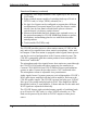
Crestron C2N-IIF Intercom Interface Intercom Interface: C2N-IIF Introduction Features and Functions The Crestron® Intercom Interface (C2N-IIF) is an interface module designed to integrate an intercom door station with a Crestron facility control system.
Intercom Interface Crestron C2N-IIF Functional Summary (continued) • Composite video output transmits video signals up to 500 feet over CAT5 cable • Eight switched outputs capable of switching loads up to 50 mA at 24 VDC each (i.e. relays, LEDS, solenoids, etc.
Crestron C2N-IIF Intercom Interface The C2N-IIF includes six logic-level inputs that can operate in one of three modes. • Essex mode: five Essex keypad panel inputs plus one discrete switch closure input for use with five-button keypads (found in select door station products) manufactured by Essex Electronics. • Matrix mode: four-by-four matrix switch closure inputs plus two discrete switch closure inputs for use with a four button-by-four button electronic keypad.
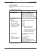
Intercom Interface Crestron C2N-IIF Specifications The following table provides a summary of specifications for the C2N-IIF. Specifications of the C2N-IIF SPECIFICATION Power Requirements Default Net ID Inputs Logic-Level Max Input Voltage Min Input Voltage Min Logic “1” Voltage Max Logic “0” Voltage Operating Modes DETAILS 20 Watts (0.83 Amp @ 24 VDC) If devices are connected to the C2N-IIF’s switched outputs and/or 24 VDC outputs, the C2N-IIF can consume up to an additional 12 Watts.
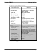
Crestron C2N-IIF Intercom Interface Specifications of the C2N-IIF (continued) SPECIFICATION Inputs (continued) Door Bell Ringer Input Type Max Input Voltage Min Input Voltage Min Logic “1” Voltage Max Logic “0” Voltage Audio Line In Input Level Video In Input Level Outputs Composite Video Out Output Level Switched Outputs Current Rating Output Drive Voltage Output On/Off Control Maximum External Drive Voltage DETAILS (1) Located at “AV IO” connector (“BELL” terminal) Logic / Switch Closure 5.5 VDC -0.
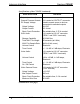
Intercom Interface Crestron C2N-IIF Specifications of the C2N-IIF (continued) DETAILS SPECIFICATION Outputs (continued) General Purpose Outputs DC Supply Voltage Output Voltage Output Current Short Circuit Protection WAV Audio Storage Capability Total WAV File Length WAV File Sample Rate Volume Control Tone Control Voice Audio Volume Control Tone Control On / Off Control Video Camera Power Output Voltage Max Output Current Short Circuit Protection Minimum Wire Size (2) Located at “OUTPUT” connector.
Crestron C2N-IIF Intercom Interface Specifications of the C2N-IIF (continued) SPECIFICATION Outputs (continued) Audio Power Amplifier Number of Channels Load Output Power THD + Noise Signal-to-Noise Ratio Frequency Response Input Source Selection Mute Recommended Speaker Microphone Audio Output Level Frequency Response Volume Control DETAILS (1) Located at “AV IO” connector (“SPK+” and “SPK-“ terminals) Single (mono) 8 Ohm speaker 13 Watts (Max average power) < 0.
Intercom Interface Crestron C2N-IIF Specifications of the C2N-IIF (continued) DETAILS SPECIFICATION Operating Temperature and Humidity Dimensions and Weight -22º to 140º F (-30º to 60º C), 10 to 90% Relative Humidity (noncondensing) Height: 5.14 in (13.06 cm) Width: 2.74 in (6.96 cm) Depth: 1.48 in (3.76 cm) Weight: 13.40 oz. (0.38 kg) 1. The latest software versions can be obtained from the Downloads | Software Updates section of the Crestron website (www.crestron.com).
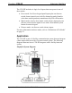
Crestron C2N-IIF Intercom Interface fastener tape, optional screws, or the optional mounting kit C2N-IIF-SPMK. For more information on installation options, refer to “Installation” on page 23. C2N-IIF Physical View (Top) Operations & Installation Guide - DOC.
Intercom Interface Crestron C2N-IIF Physical Views of the C2N-IIF Ports All connections to the C2N-IIF are made through the ports on the front and side of the enclosure. Refer to the following diagrams and descriptions of each port. NOTE: Interface connectors for the NET, AV IO, INPUT, and OUTPUT ports are provided with the C2N-IIF. 10 • Intercom Interface: C2N-IIF Operations & Installation Guide - DOC.
Crestron C2N-IIF Intercom Interface NOTE: Images shown are for illustrative purposes only. VIDEO (OUT) This RJ-45 connector supplies a balanced composite video signal from the door station camera (if equipped) to a Crestron C2N-IVDS24x24 or any other device that receives balanced composite video over CAT5 cable.
Intercom Interface Crestron C2N-IIF RJ-45 Connector Specifications TYPE PIN SIGNALS 8-Position RJ-45 1 Line level MIC OUT + Line level MIC OUT N/A Line Level Audio In + Line Level Audio In N/A N/A N/A 2 3 4 5 6 7 8 1 8 1 8 Top Front NOTE: For additional information on audio/video connections over CAT5, refer to the latest version of the Crestron CAT5 Wiring Reference Guide (Doc. 6137) which is available from the Downloads | Product Manuals section of the Crestron website (www.crestron.com).
Crestron C2N-IIF Intercom Interface Pin Assignments for Input Port PIN WIRE COLOR ESSEX (Mode 0) MATRIX (Mode 1) DISCRETE (Mode 2) 1 Black N/A N/A 2 Red N/A N/A 3 White 4 Green 5 Orange 6 Blue 7 Brown 8 Yellow Matrix Row 1 Matrix Row 4 Matrix Row 2 Discrete Input 1 Matrix Row 3 N/A Discrete Input 1 Discrete Input 4 Discrete Input 2 Discrete Input 5 Discrete Input 3 Ground 9 Violet N/A Ground 10 Gray N/A Ground 11 Pink N/A N/A 12 Tan Essex Pin 1 Essex Pin 2 Essex Pi
Intercom Interface Crestron C2N-IIF OUTPUT This 14-position male connector can be configured via software to provide up to eight switched outputs (50 mA max at 24 VDC per output) for devices connected to the C2N-IIF. Two general-purpose outputs (500 mA total at 24 VDC) are also provided to power devices that are switched by the C2N-IIF’s switched outputs or other devices that require a 24 VDC signal. A 12-inch connecting cable is supplied.
Crestron C2N-IIF Intercom Interface Pin Assignments for Output Port (continued) PIN IN WIRE ESSEX COLOR (Mode 0) 6 Blue Discrete Output 6 7 Brown Discrete Output 7 8 Yellow Discrete Output 8 9 10 Violet Gray 11 12 Pink Tan 13 RedGreen RedYellow Ground +24 VDC Ground +24 VDC Ground 14 MATRIX (Mode 1) DISCRETE (Mode 2) Matrix Input Column 2 Matrix Input Column 3 Matrix Input Column 4 N/A +24 VDC Discrete Output 6 Ground +24 VDC N/A +24 VDC Ground +24 VDC N/A Ground N/A Ground G
Intercom Interface Crestron C2N-IIF AV IO This nine-position terminal block connector is used to receive a microphone’s output signal, a video camera’s output signal, and a doorbell switch closure. This connector also provides 12 VDC power to a video camera (if equipped), and speaker-level audio to a door station speaker. Indicators, Buttons, and Controls The indicators, buttons, and controls of the C2N-IIF are described in the following paragraphs.
Crestron C2N-IIF Intercom Interface Industry Compliance As of the date of manufacture, the C2N-IIF has been tested and found to comply with specifications for CE marking and standards per EMC and Radiocommunications Compliance Labelling (N11785). NOTE: This device complies with part 15 of the FCC rules.
Intercom Interface Crestron C2N-IIF The required wire gauge should be chosen such that the resistance value is less than the value calculated in the resistance equation. Refer to the following table. Wire Gauge Values RESISTANCE (R) WIRE GAUGE 4 16 6 18 10 20 15 22 13 Doubled CAT5 8.7 Tripled CAT5 NOTE: All Cresnet wiring must consist of two twisted-pairs. One twisted pair is the +24V conductor and the GND conductor and the other twisted pair is the Y conductor and the Z conductor.
Crestron C2N-IIF Intercom Interface Hardware Hookup for the C2N-IIF OUTPUT: TO SWITCHED DEVICES (RELAYS, SOLENOIDS, ETC.
Intercom Interface Crestron C2N-IIF Identity Code All equipment and user interfaces within the network require a unique identity code (Net ID). These codes are two-digit hexadecimal numbers from 03 to FE. The Net ID of each unit must match an ID code specified in the SIMPL Windows program. Refer to “Setting the Net ID in Device Settings” on page 27 for details of the SIMPL Windows procedure. Refer to the note on page 36 for a definition of Viewport. The Net ID of the C2N-IIF has been factory set to 19.
Crestron C2N-IIF Intercom Interface 3. From the Viewport menu, select Functions | Set Network ID. The software checks the baud rate and then opens the "Set Network ID" window. 4. In the "Set Network ID" window, select the device requiring a Net ID change from the Current Network Devices text window. 5. Select the new Net ID for the device from the Choose the new network ID for the selected device (Hex): text box. 6. Click Set ID to initiate the change.
Intercom Interface 4. Crestron C2N-IIF Click on the Search for Touch Settable Devices button. The system searches the network and lists all TSID-enabled devices found. The list is similar to the report produced by pressing F4 (Report Network Devices); the first eight digits of each line constitute the TSID number (hexadecimal form of the serial number). “Set Net ID by TSID” Window 5. Enter either the serial number or TSID number of the device that requires a change.
Crestron C2N-IIF Intercom Interface the TSID but not the serial number, and your site installation list is based on device serial numbers. In this (or the reverse) situation, do the following: 1. Open the Crestron Viewport. 2. From the Viewport menu, select Functions | Serial Number ÅÆ TSID Conversion Tool. The “Serial Number ÅÆTSID Conversion Tool” window is displayed. “Serial Number to TSID Conversion Tool” Window 3.
Intercom Interface Crestron C2N-IIF Programming Software Have a question or comment about Crestron software? Answers to frequently asked questions (FAQs) can be viewed in the Online Help section of the Crestron website (www.crestron.com). Go to http://support.crestron.com to post your own question or view questions you have submitted to Crestron’s True Blue Support. First-time users will need to establish a user account.
Crestron C2N-IIF Intercom Interface .usp projectname.usp (source code module for SIMPL+) .umc projectname.umc (user macro for SIMPL) SIMPL Windows is Crestron's primary software for programming Crestron control systems. It provides a well-designed graphical environment with a number of workspaces (i.e., windows) in which a programmer can select, configure, program, test, and monitor a Crestron control system. SIMPL Windows offers drag and drop functionality in a familiar Windows environment.
Intercom Interface Crestron C2N-IIF Expanded PRO2 System Tree C2Net-Device Slot in Configuration Manager To incorporate the C2N-IIF into the system, drag the C2N-IIF from the Cresnet Control Modules | Cresnet I/O Control & Other Modules folder of the Device Library and drop it in the System Views. The PRO2 system tree displays the device in slot 9 with a default Net ID of 19 as shown in the following illustration.
Crestron C2N-IIF Intercom Interface Setting the Net ID in Device Settings Double-click the C2N-IIF icon to open the “Device Settings” window. This window displays the C2N-IIF device information. If necessary, select the Net ID tab to change the Net ID, as shown in the following figure. “Device Settings” Window for the C2N-IIF NOTE: SIMPL Windows automatically changes Net ID values of a device added to a program if a duplicate device or a device with the same default Net ID already exists in the program.
Intercom Interface Crestron C2N-IIF C2N-IIF Symbol in SIMPL Windows Programming Manager NOTE: The symbol image has been altered to fit the page. 28 • Intercom Interface: C2N-IIF Operations & Installation Guide - DOC.
Crestron C2N-IIF Intercom Interface The following tables list the symbol’s input and output signals, respectively, and their functional descriptions. C2N-IIF Digital Input Signal Descriptions INPUT DESCRIPTION Output1_On/Off through Output8_On/Off When high, the respective switched output will close. In Essex and Discrete mode, all eight outputs are available. In Matrix mode, only outputs 1 through 4 are available, while outputs 5 through 8 are reserved to enable four-by-four matrix switching.
Intercom Interface Crestron C2N-IIF Signal Values for “IO_MODE_Select” SIGNAL VALUE 0 1 2 MODE Selects Essex Mode. Selects Matrix Mode. Selects Discrete I/O Mode. Refer to “Definitions of IO Modes” on page 31 for an explanation of each of the IO modes. C2N-IIF Digital Output Signal Descriptions INPUT DESCRIPTION DoorBellBtn Goes high when door bell switch closes (pushed) for as long as the signal remains high. Goes high when a WAV file is playing. Remains high for as long as the WAV file is playing.
Crestron C2N-IIF Intercom Interface C2N-IIF Input Press Definitions INPUT PRESS ESSEX MODE MATRIX MODE DISCRETE MODE 1 2 3 4 5 6 7 8 9 10 11 12 13 14 15 16 17 18 Essex Button 1_2 Essex Button 3_4 Essex Button 5_6 Essex Button 7_8 Essex Button 9_0 Discrete 1 Press N/A N/A N/A N/A N/A N/A N/A N/A N/A N/A N/A N/A Row 1, Column 1 Row 1, Column 2 Row 1, Column 3 Row 1, Column 4 Row 2, Column 1 Row 2, Column 2 Row 2, Column 3 Row 2, Column 4 Row 3, Column 1 Row 3, Column 2 Row 3, Column 3 Row 3, Column 4
Intercom Interface Crestron C2N-IIF Essex Keypad with Signal Names Matrix Mode The matrix mode is designed for keypads with more than six buttons, to a maximum of 16 buttons (as shown in the following diagram). In this mode four of the digital inputs and four of the outputs are reserved to enable 4x4 matrix switching. This leaves two digital inputs and four switched outputs available for other purposes.
Crestron C2N-IIF Intercom Interface Device Extenders Device extenders provide additional logic and functionality to a device. The Poll Manager symbol is a device extender for the C2N-IIF. Poll Manager takes the C2N-IIF on and off line during polling by the control system. For additional information about Device Extenders, refer to the latest version of the Crestron SIMPL Windows Symbol Guide (Doc. 6120), or the on-line help included with SIMPL Windows.
Intercom Interface Crestron C2N-IIF the C2N-IIF directly or may be edited with the Sound Recorder. For example, the individual files can be combined to create custom messages. NOTE: WAV files can be obtained from the Crestron FTP site (ftp.crestron.com/Wave LC/). Sound Manager Crestron VT Pro-e (version 2.1.0 and later) contains an audio tool, Sound Manager, which permits the panel designer to attach WAV files to a touchpanel project.
Crestron C2N-IIF Intercom Interface Sound Manager Guidelines There are two things to keep in mind when using Sound Manager. 1. Each WAV file must be assigned a unique digital join number. The join number options include none, or a number (13 for WAV file 1 through 42 for WAV file 30). The default is none. The other WAV files can be played by having the SIMPL Windows program assert the assigned join number. 2.
Intercom Interface Crestron C2N-IIF NOTE: When specifying a join, only join numbers 13 through 42 can be assigned to WAV files. Join number 13 corresponds to WAV1, join 14 corresponds to WAV2, etc. NOTE: To remove a WAV file from the Sound List table, highlight the file and click on the Remove button. The Properties button opens the “Sound Properties” window for a highlighted WAV file in the Sound List table.
Crestron C2N-IIF Intercom Interface The following sections define how one would upload a SIMPL Windows program, a VT Pro-e project, or upgrade the firmware of the C2N-IIF. However, before attempting to upload or upgrade, it is necessary to establish communications with the control system. Communication Settings NOTE: For laptops and other PCs without a built-in RS-232 port, Crestron recommends the use of PCMCIA cards, rather than USB-toserial adapters.
Intercom Interface Crestron C2N-IIF Typical Connection Diagram when Uploading 1. Open the Crestron Viewport. Either launch the stand-alone version of Viewport, or start SIMPL Windows or VT Pro-e and from the menu bar, select Tools | Viewport. 2. Refer to the figure after this step. From the Viewport menu, select Setup | Communications settings (alternatively, press Alt+D) to open the “Port Settings” window.
Crestron C2N-IIF Intercom Interface 3. Select RS-232 as the connection type. Verify that an available COM port (COM 1 is shown after this step) is selected, and that all communication parameters and necessary options from the “Port Settings” window are selected as shown after this step. Click the OK button to save the settings and close the window. “Port Settings” Window NOTE: The parameters shown in the illustration above are the port settings for a 2-Series control system.
Intercom Interface 4. Crestron C2N-IIF To verify communication, select Diagnostics | Establish Communications (Find Rack). This should display a window that gives the COM port and baud rate. If communication cannot be established, refer to the “Troubleshooting Communications” section in the respective Operations Guide for the control system. Uploading a SIMPL Windows Program A control system source file has the extension .smw. A compiled SIMPL Windows file has the extension .
Crestron C2N-IIF Intercom Interface any SIMPL+ modules, only the SIMPL Program check box will be enabled. If it does contain SIMPL+ modules, then the SIMPL+ Program(s) check box will also be enabled. Select one or both check boxes and then click Send Program to begin the transfer. NOTE: Refer to the respective Operations Guide for the control system for details about the other fields shown on the “Send Program” window. “Send Program” Window 4.
Intercom Interface Crestron C2N-IIF Uploading a VT Pro-e Project The C2N-IIF Intercom Interface source file has the extension .vtp. A compiled VT Pro-e file has the extension .hex. The VT Pro-e file can be uploaded to the C2N-IIF using VT Pro-e or via the Crestron Viewport. Upload via VT Pro-e 1. Start VT Pro-e. 2. Select File | Open | Project to view the “Open” window, navigate to the VT Pro-e file (.vtp), and click Open. 3. Select File | Upload Project. This automatically selects the compiled .
Crestron C2N-IIF Intercom Interface “Select Network ID” Window NOTE: If problems occur when transferring any Cresnet file (touchpanel project/firmware), lower the port speed baud rate to 38400 to match the Cresnet bus speed when transferring through a control system. “Open” Window 4. Select the compiled file (.hex) file and click Open. The transfer will complete automatically. Operations & Installation Guide - DOC.
Intercom Interface Crestron C2N-IIF Firmware Upgrade A firmware upgrade file has the extension .csf. To take advantage of all of the C2N-IIF features, it is important that the unit contains the latest firmware available. Please check the Crestron website (http://www.crestron.com/downloads/software_updates.asp) for the latest version of firmware.
Crestron C2N-IIF 3. Intercom Interface As shown in the “Select Network ID” window, select the Net ID of the C2N-IIF, and then click OK. The “Open” window appears (refer to the following graphics). “Select Network ID” Window NOTE: If problems arise when transferring any Cresnet file (touchpanel project/firmware), lower the port speed baud rate to 38400 to match the Cresnet bus speed. “Open” Window 4. Browse to the desired [filename].upg file and click Open to begin the transfer.
Intercom Interface Crestron C2N-IIF Problem Solving Troubleshooting The following table provides corrective action for possible trouble situations. If further assistance is required, please contact a Crestron customer service representative. C2N-IIF Troubleshooting TROUBLE C2N-IIF does not function. POSSIBLE CAUSE(S) C2N-IIFis not receiving power. C2N-IIF Net ID is not correct. C2N-IIF Net ID is not set to match the Net ID specified in SIMPL Windows. C2N-IIF Net ID is the same as another device’s Net ID.
Crestron C2N-IIF Intercom Interface C2N-IIF Troubleshooting (continued) TROUBLE POSSIBLE CAUSE(S) CORRECTIVE ACTION C2N-IIF switched outputs do not function. C2N-IIF is set to the wrong operating mode. Set correct operating mode (see “C2N-IIF Symbol in Programming Manager" on page 27). Rewire OUTPUT connector for desired operating mode (see “OUTPUT" on page 14). C2N-IIF OUTPUT connector is wired incorrectly for operating mode.
Intercom Interface Crestron C2N-IIF Future Updates As Crestron improves functions, adds new features, and extends the capabilities of the C2N-IIF, additional information may be made available as manual updates. These updates are solely electronic and serve as intermediary supplements prior to the release of a complete technical documentation revision. Check the Crestron website (www.crestron.com) periodically for manual update availability and relevance.
Crestron C2N-IIF Intercom Interface Return and Warranty Policies Merchandise Returns / Repair Service 1. No merchandise may be returned for credit, exchange, or service without prior authorization from CRESTRON. To obtain warranty service for CRESTRON products, contact the factory and request an RMA (Return Merchandise Authorization) number. Enclose a note specifying the nature of the problem, name and phone number of contact person, RMA number, and return address. 2.
Intercom Interface Crestron C2N-IIF This page intentionally left blank. 50 • Intercom Interface: C2N-IIF Operations & Installation Guide - DOC.
Crestron C2N-IIF Intercom Interface This page intentionally left blank. Operations & Installation Guide - DOC.
Crestron Electronics, Inc. 15 Volvo Drive Rockleigh, NJ 07647 Tel: 888.CRESTRON Fax: 201.767.7576 www.crestron.com Operations Guide - DOC. 6235 04.04 Specifications subject to change without notice.