
User Guide

Crestron C2N-IIF Intercom Interface
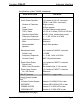
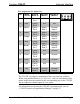
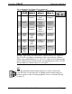
Pin Assignments for Input Port
PIN WIRE
COLOR
ESSEX
(Mode 0)
MATRIX
(Mode 1)
DISCRETE
(Mode 2)
1 Black Essex
Pin 1
N/A N/A
2 Red Essex
Pin 2
N/A N/A
3 White Essex
Pin 3
Matrix
Row 1
Discrete
Input 1
4 Green Essex
Pin 4
Matrix
Row 4
Discrete
Input 4
5 Orange Essex
Pin 5
Matrix
Row 2
Discrete
Input 2
6 Blue Essex
Pin 6
Discrete
Input 1
Discrete
Input 5
7 Brown Essex
Pin 7
Matrix
Row 3
Discrete
Input 3
8 Yellow Essex
Pin 8
N/A Ground
9 Violet Essex
Pin 9
N/A Ground
10 Gray Essex
Pin 10
N/A Ground
11 Pink Essex
Pin 11
N/A N/A
12 Tan Discrete
Input 1
Discrete
Input 2
Discrete
Input 6
NOTE: When using the Matrix mode, smaller matrices are supported.
The C2N-IIF can support a maximum of four rows and four columns.
When using smaller matrices (i.e. 4x3, 3x3), each row and column of the
matrix output must be matched to the corresponding port on the C2N-IIF.
Do not connect a column output to a row input.
For information on selecting the C2N-IIF’s operating mode, refer to
“C2N-IIF Symbol in Programming Manager” on page 27.
Operations & Installation Guide - DOC. 6235 Intercom Interface: C2N-IIF • 13