
User Guide

Intercom Interface Crestron C2N-IIF
OUTPUT
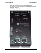
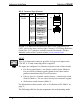
This 14-position male connector can be configured via software to
provide up to eight switched outputs (50 mA max at 24 VDC per output)
for devices connected to the C2N-IIF. Two general-purpose outputs (500
mA total at 24 VDC) are also provided to power devices that are
switched by the C2N-IIF’s switched outputs or other devices that require
a 24 VDC signal. A 12-inch connecting cable is supplied.
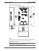
NOTE: Devices connected to the switched outputs can be powered by
the C2N-IIF’s general outputs at pins 10 and 12, or can be powered
externally. If devices are connected to all of the switched outputs and are
powered by the general outputs, each switched output is capable of
driving a 50 mA at 24 VDC (maximum) load (0.4 A total). An additional
0.1 A at 24 VDC is still available from the general output.
NOTE: If devices connected to the switched outputs are powered
externally, the general outputs on pins 10 and 12 can drive a 0.5 A
maximum load at 24 VDC. Each switched output is still rated at 50 mA
at 24 VDC).
The output port operates in the mode specified for the input port. Refer to
“INPUT” on page 12 for more information on the input port’s operating
mode.
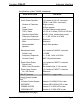
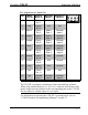
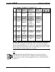
The following table lists the pin assignments for each operating mode.
Pin Assignments for Output Port
PIN WIRE
COLOR
ESSEX
(Mode 0)
MATRIX
(Mode 1)
DISCRETE
(Mode 2)
1 Black Discrete
Output 1
Discrete
Output 1
Discrete
Output 1
2 Red Discrete
Output 2
Discrete
Output 2
Discrete
Output 2
3 White Discrete
Output 3
Discrete
Output 3
Discrete
Output 3
4 Green Discrete
Output 4
Discrete
Output 4
Discrete
Output 4
5 Orange Discrete
Output 5
Matrix Input
Column 1
Discrete
Output 5
(continued on next page)
14 • Intercom Interface: C2N-IIF Operations & Installation Guide - DOC. 6235