
User Guide

Crestron C2N-IIF Intercom Interface
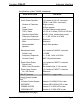
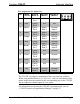
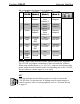
Pin Assignments for Output Port (continued)
PIN IN WIRE
COLOR
WIRE
COLOR
ESSEX
(Mode 0)
ESSEX
(Mode 0)
MATRIX
(Mode 1)
MATRIX
(Mode 1)
DISCRETE
(Mode 2)
DISCRETE
(Mode 2)
6 Blue Discrete
Output 6
Matrix
Input
Column 2
Discrete
Output 6
7 Brown Discrete
Output 7
Matrix
Input
Column 3
Discrete
Output 7
8 Yellow Discrete
Output 8
Matrix
Input
Column 4
Discrete
Output 8
9 Violet Ground N/A Ground
10 Gray +24
VDC
+24 VDC +24 VDC
11 Pink Ground N/A Ground
12 Tan +24
VDC
+24 VDC +24 VDC
13 Red-
Green
Ground N/A Ground
14 Red-
Yellow
Ground N/A Ground
NOTE: When using the Matrix mode, smaller matrices are supported.
The C2N-IIF can support a maximum of four rows and four columns.
When using smaller matrices (i.e. 4x3, 3x3), each row and column of the
matrix output must be matched to the corresponding port on the C2N-IIF.
Do not connect a column output to a row input.
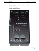
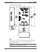
NET
This four-position terminal block connector is used to connect the
C2N-IIF to the Cresnet network. If making network connections to a
control system or other Cresnet peripherals, refer to “Network Wiring”
on page 15.
Operations & Installation Guide - DOC. 6235 Intercom Interface: C2N-IIF • 15