
User Guide

Intercom Interface Crestron C2N-IIF
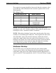
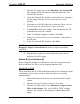
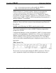
The required wire gauge should be chosen such that the resistance value
is less than the value calculated in the resistance equation. Refer to the
following table.
Wire Gauge Values
RESISTANCE (R) WIRE GAUGE
4
16
6
18
10
20
15
22
13
Doubled CAT5
8.7
Tripled CAT5
NOTE: All Cresnet wiring must consist of two twisted-pairs. One
twisted pair is the +24V conductor and the GND conductor and the other
twisted pair is the Y conductor and the Z conductor.
NOTE: When daisy-chaining Cresnet units, strip the ends of the wires
carefully to avoid nicking the conductors. Twist together the ends of the
wires that share a pin on the network connector, and tin the twisted
connection. Apply solder only to the ends of the twisted wires. Avoid
tinning too far up the wires or the end becomes brittle. Insert the tinned
connection into the Cresnet connector plug and tighten the retaining
screw. Repeat the procedure for the other three conductors.
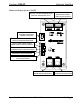
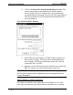
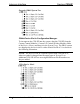
Hardware Hookup
The C2N-IIF serves as an interface between a door station and the
Cresnet system. Refer to the illustration after this paragraph for proper
connections; apply power last. When making network connections to a
control system or Cresnet peripherals, refer to “Network Wiring” on page
17.
18 • Intercom Interface: C2N-IIF Operations & Installation Guide - DOC. 6235