
Installation guide
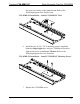
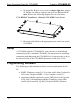

Scan Converter Card for C2N-MMS Crestron C2N-MMS-SC
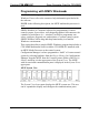
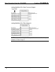
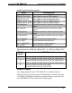
Digital Output Signal Descriptions
OUTPUT DESCRIPTION
RGB_In_1_Sense Goes high when signal detected on RGB Input 1.
RGB_In_2_Sense Goes high when signal detected on RGB Input 2.
RGB_In_3_Sense Goes high when signal detected on RGB Input 3.
RGB_In_4_Sense Goes high when signal detected on RGB Input 4.
VIDEO_In_1_Sense Goes high when signal detected on VIDEO Input 1.
VIDEO_In_2_Sense Goes high when signal detected on VIDEO Input 2.
VIDEO_In_3_Sense Goes high when signal detected on VIDEO Input 3.
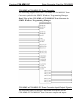
Digital Input Signal Descriptions
INPUT DESCRIPTION
Cable-EQ1-Out1* Turns on EQ1 level signal compensation on
RGB Output 1.
Cable-EQ2-Out1* Turns on EQ2 level signal compensation on
RGB Output 1.
Boost-Out1* Turns on 3 dB signal boost on RGB Output 1.
Cable-EQ1-Out2* Turns on EQ1 level signal compensation on
RGB Output 2.
Cable-EQ2-Out2* Turns on EQ2 level signal compensation on
RGB Output 2.
Boost-Out2* Turns on 3 dB signal boost on RGB Output 2.
SC-PAL When high, sends scan converter output in PAL
format. When low, output is in NTSC format.
SC-Composite Sends scan converter output as composite
video signal. When low, output is S-video.
Test_Pattern Sends a test pattern through scan converter
output. This will override scan converter output.
* Information on Cable-EQ & Boost signals can be found in the latest revision of the C2N-MMS
Professional Multimedia Switch Installation Guide (Doc. 6132).
NOTE: Different combinations of signal compensation and boosting are
recommended for different lengths of RGB Cable. Refer to the latest
revision of the C2N-MMS Operations Guide (Doc. 6132) for more
information.
14 • Scan Converter Card for C2N-MMS: C2N-MMS-SC Operations & Installation Guide - DOC. 6138