
User Guide


Table Of Contents
Crestron C2N-MMS Professional Multimedia Switch
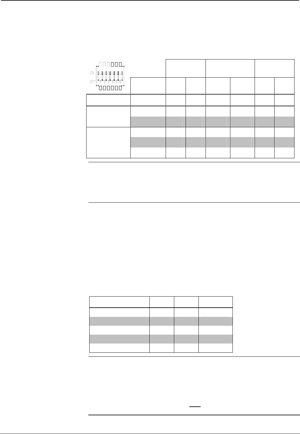
Setting the DIP Switches
1. Referring to the following table, set the DIP switches to the required sync
input impedance and DDC functionality of each RGB input port.
DIP Switch Function Chart
DDC HORIZONTAL
SYNC
VERTICAL
SYNC
SWITCH
1 2 3 4 5 6
FUNCTION SETTING
OFF OFF OFF X X X X
DDC
ON ON ON X X X X
1K X X OFF OFF OFF OFF
500 X X ON OFF ON OFF
SYNC INPUT
IMPEDANCE
75 X X ON ON ON ON
NOTE: The function table is also located on the C2N-MMS adjacent to the DIP
switches.
NOTE: The factory setting for the DIP switches are DDC disabled (switches 1 & 2
in the OFF position) and 1k ohm impedance (switches 3 through 6 in the OFF
position).
2. Replace the top cover and secure the screws using the #2 Phillips
screwdriver.
RGB Signal Compensation
To account for varying cable lengths for RGB output signals, the C2N-MMS features
switchable 3 dB frequency compensation and 1.25 dB signal boost to provide clear
images on cable runs over 100 feet. The following table illustrates which settings to
use for specific RGB cable lengths. All settings are made from the control system
program. Refer to “Programming Software” on page 15 for more information.
Cable Length and Suggested EQ/Boost Settings
CABLE LENGTH EQ1 EQ2 BOOST
0 to 25 ft Off Off Off
25 to 50 ft On Off Off
50 to 75 ft Off On Off
75 to 100 ft On On Off
More than 100 On On On
NOTE: The sync output is not affected by peak and boost settings.
NOTE: These settings are only suggested settings. Results may vary depending on
the type of cable and installation methods used. The user should determine the
settings for best results in specific installations.
NOTE: Crestron has successfully tested 100-foot cable runs without loss of picture
quality. Cable runs in excess of 100 feet may
be subject to signal degradation as
cable length increases over 100 feet.
Operations Guide – DOC. 6374 Professional Multimedia Switch: C2N-MMS • 13