Crestron CHV-TSTAT & CHV-THSTAT Thermostats Operations and Installation Guide
This document was prepared and written by the Technical Documentation department at: Crestron Electronics, Inc. 15 Volvo Drive Rockleigh, NJ 07647 1-888-CRESTRON All brand names, product names and trademarks are the property of their respective owners. ©2004 Crestron Electronics, Inc.
Crestron CHV-TSTAT and CHV-THSTAT Thermostats Contents Quick Installation Reference ....................................................................................................iii Thermostats: CHV-TSTAT and CHV-THSTAT 1 Introduction ............................................................................................................................... 1 Functions and Features ................................................................................................
Thermostats Crestron CHV-TSTAT and CHV-THSTAT Viewport Error Log Message Formats ...................................................................... 83 Local Error Messages ................................................................................................ 84 Problem Solving ...................................................................................................................... 85 Troubleshooting..................................................................................
Crestron CHV-TSTAT and CHV-THSTAT Thermostats Quick Installation Reference 1. Select a suitable location and run the connecting wires from the heating/cooling system and the Cresnet system. Refer to page 5 for a description of the thermostat connectors. Refer to page 7 for Network wiring details.
Crestron CHV-TSTAT and CHV-THSTAT Thermostats Thermostats: CHV-TSTAT and CHV-THSTAT Introduction Functions and Features The CHV-TSTAT and CHV-THSTAT series are wall-mounted universal thermostats that can be part of a Crestron Home® total control system. The thermostats are capable of controlling one or two-stage heating and cooling systems. Each thermostat is available in three colors: almond, black and white. The suffix ‘A’, ‘B’, and ‘W’, respectively denotes color, e.g., CHV-TSTATB is a black unit.
Thermostats Crestron CHV-TSTAT and CHV-THSTAT Firmware Versions The new features, and consequent changes to the SIMPL Windows symbol programming, for firmware version 2.0 and later make it incompatible for use with X-generation control processors. In addition, upgrading to release 2.0 and later from a previous release will require a complete re-programming of the thermostat. Remote Sensors Firmware version 2.
Crestron CHV-TSTAT and CHV-THSTAT Thermostats Specifications The following table provides a summary of specifications for the CHV-TSTAT and CHV-THSTAT. CHV-TSTAT and CHV-THSTAT Specifications SPECIFICATION DETAILS Power Requirements 2 Watts (24 VAC @ 83mA) Heating or Cooling System Supplied Crestron power factor <1 Watt (required for Cresnet communication only) Default Network ID Control System Update Files 2A 1,2 2-Series Control System Version 3.080.
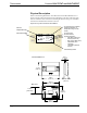
Thermostats Crestron CHV-TSTAT and CHV-THSTAT Physical Description Refer to the following illustrations. The CHV-TSTAT and CHV-THSTAT are in a plastic enclosure with four buttons and an LCD display on the front. The back of the unit has ventilation slots, and holes for mounting the unit and wiring. The ventilation slots must be unobstructed for airflow to the unit.
Crestron CHV-TSTAT and CHV-THSTAT Thermostats Connection View (Backplate, view from the front with cover removed) Z G 24V Y 24(C) 24(R) RS2 RS1 RSR RSR HUM RHU TOP W2 W/W1 B O Y2 Y/Y1 G RC RH NETWORK Ports The CHV-TSTAT and CHV-THSTAT have four types of connections on the inside back plate (refer to graphic above). NETWORK (Optional) – provides communication to the control system and Cresnet power to the CHV-TSTAT and CHV-THSTAT.
Thermostats Crestron CHV-TSTAT and CHV-THSTAT Control Connections (System Dependent) PIN DESCRIPTION HUM Energized to RHU during humidity call RHU Reference for humidifier RH Reference Heat, used for calls to heating system RC Reference Cool, used for calls to cooling system G Y/Y1 Y2 Fan, energized to RC during call for fan Compressor (stage one), energized to RC when compressor (or first stage) is run Compressor (stage two), energized to RC on two-stage systems on call for second stage O C
Crestron CHV-TSTAT and CHV-THSTAT Thermostats Setup Network Wiring CAUTION: In order to ensure optimum performance over the full range of your installation topology, Crestron Certified Wire, and only Crestron Certified Wire, should be used. Failure to do so may incur additional charges if support is required to identify performance deficiencies as a result of using improper wire. CAUTION: Use only Crestron power supplies for Crestron equipment.
Thermostats Crestron CHV-TSTAT and CHV-THSTAT System Connections NOTE: Installers should have a strong working knowledge of HVAC systems.
Crestron CHV-TSTAT and CHV-THSTAT Thermostats the SIMPL Windows procedure. The Net ID of the Thermostats has been factory set to 2A. The Net IDs of multiple thermostats in the same system must be unique. Net IDs are changed from a personal computer (PC) via the Crestron Viewport. NOTE: The Crestron Viewport is available as a pull-down command from SIMPL Windows and VisionTools® Pro-e (Tools | Viewport) or as a standalone utility.
Thermostats Crestron CHV-TSTAT and CHV-THSTAT 6. Click Set ID to initiate the change. This will display the "ID command has been sent" window. 7. In the "Command Complete" window, click OK. 8. In the Current Network Devices text window, verify the new Net ID code. 9. In the "Set Network ID" window, click Close. NOTE: The new Net ID code may also be verified by selecting Diagnostic | Report Network Devices in the Viewport (alternately, select F4). 10.
Crestron CHV-TSTAT and CHV-THSTAT Thermostats 5. Enter either the serial number or TSID number of the device that requires a change. The list scrolls to and highlights the device listing. The listing should show the device’s default Cresnet ID (a.k.a. Net ID). 6. Enter the Cresnet ID that the device should be set to and click OK. The number you enter should appear on the list. CAUTION: This function does not prevent you from setting duplicate IDs.
Thermostats Crestron CHV-TSTAT and CHV-THSTAT Wiring Diagrams The wiring diagrams that follow show connections for the CHV-TSTAT and CHV-THSTAT. The heating or cooling system can supply power to the thermostat, or a separate transformer can supply it. In many installations, spare conductors are available to supply 24 VAC to the thermostat, using the C (24 VAC common) connection on the HVAC equipment.
Crestron CHV-TSTAT and CHV-THSTAT Thermostats Separately Powered Two Wire Heat (Powered by an Independent Transformer) Independent Transformer Connection – P4 Jumper Connects Pins 2 and 3 Single Stage Heat Only Single Stage Heat Only System Powered – P4 Jumper Connects Pins 1 and 2 Operations and Installation Guide – DOC.
Thermostats Crestron CHV-TSTAT and CHV-THSTAT Single Stage Heat with Fan Control Single Stage Heat with Fan Control – P4 Connects Pins 1 and 2 – Additional Jumper Connects RH to RC Single Stage Cool Only Single Stage Cool Only – P4 Jumper Connects Pins 3 and 4 14 • Thermostats: CHV-TSTAT and CHV-THSTAT Operations and Installation Guide – DOC.
Crestron CHV-TSTAT and CHV-THSTAT Thermostats Single Stage Heat/Cool with Integrated Control Unit Single Stage Heat/Cool with Integrated Control Unit – P4 Jumper Connects Pins 1 and 2 – Additional Jumper RH to RC Operations and Installation Guide – DOC.
Thermostats Crestron CHV-TSTAT and CHV-THSTAT Single Stage Heat/Cool with Separate Systems Single Stage Heat/Cool with Separate Systems – Heating System Powered – P4 Jumper Connects Pins 1 and 2 16 • Thermostats: CHV-TSTAT and CHV-THSTAT Operations and Installation Guide – DOC.
Crestron CHV-TSTAT and CHV-THSTAT Thermostats Single Stage Heat Pump Single Stage Heat Pump – P4 Jumper Connects Pins 3 and 4– Additional Jumper RH to RC Operations and Installation Guide – DOC.
Thermostats Crestron CHV-TSTAT and CHV-THSTAT Two Stage Heat Pump Two Stage Heat Pump System – P4 Jumper Connects Pins 3 and 4 – Additional Jumper RH to RC 18 • Thermostats: CHV-TSTAT and CHV-THSTAT Operations and Installation Guide – DOC.
Crestron CHV-TSTAT and CHV-THSTAT Thermostats Slab 1, Slab 2, and Slab 3 Systems (Floor Warming and/or Space Heating) Slab 1, Slab 2, and Slab 3 Systems (Floor Warming and/or Space Heating) – P4 Jumper Connects Pins 1 and 2 Operations and Installation Guide – DOC.
Thermostats Crestron CHV-TSTAT and CHV-THSTAT Slab 4A Two Stage Heat/Single Stage Cool Systems, Slab 5A Floor Warming with Single Stage Space Heat/Cool Heat/Cool Style Connections Slab 4A – P4 Jumper Connects Pins 1 and 2 – Jumper Connects RH to RC 20 • Thermostats: CHV-TSTAT and CHV-THSTAT Operations and Installation Guide – DOC.
Crestron CHV-TSTAT and CHV-THSTAT Thermostats Slab 4B Two Stage Heat/Single Stage Cool System, Slab 5B Single Stage Heat/Cool with Floor Warming Heat Pump Style Connections Slab 4B – P4 Jumper Connects Pins 3 and 4 – Additional Jumper Connects RH to RC Operations and Installation Guide – DOC.
Thermostats Crestron CHV-TSTAT and CHV-THSTAT General Humidifier Connections 22 • Thermostats: CHV-TSTAT and CHV-THSTAT Operations and Installation Guide – DOC.
Crestron CHV-TSTAT and CHV-THSTAT Thermostats Installation The location of the thermostat can affect its performance and efficiency. Install the thermostat away from direct sunlight, drafts, doorways, skylights, and windows. Also make sure the thermostat is conveniently located for programming, and do not mount on an exterior wall. The thermostats may be mounted directly to drywall or to a single-gang box. Thermostats and sensors are mounted 60 inches (152.
Thermostats Crestron CHV-TSTAT and CHV-THSTAT Installation View – Single gang electrical box – horizontal mounting NOTE: Install insulation in the gang box to prevent inaccurate readings. Stud Panhead 6/32 x 1 in Single-gang electrical box (not provided) Installation view – Direct mount to wall Wall Anchors (not provided) Mounting Screws (not provided) 24 • Thermostats: CHV-TSTAT and CHV-THSTAT Backplate Operations and Installation Guide – DOC.
Crestron CHV-TSTAT and CHV-THSTAT Thermostats Thermostat Setup and Operation Setup Procedure After the thermostat is installed, it is necessary to set it up for a particular heating/cooling system. There are nine types of heating and cooling systems. Each system type is setup using nine screens. The available choices displayed on the setup screens depend on the type of system selected. Follow these directions to access the setup screens. 1.
Thermostats Crestron CHV-TSTAT and CHV-THSTAT NOTE: If an out-of-range setpoint is entered, the setpoint is assigned its limit value in that direction. NOTE: The Screen Options selected in setup are seen when the view key is pressed in normal operation. System Types and Definitions The first setup choice is the heat system type. There are three main types of heating/cooling systems. 1. Heat/Cool, Radiant Heat or Forced Air Heating/Cooling, 1 or 2 Stages 2.
Crestron CHV-TSTAT and CHV-THSTAT 3. Thermostats Slab Systems Slab heating works from the ground up. The heating components are installed below the floor or are embedded in a concrete slab. Heat radiates from the floor to warm the space above. The CHV-TSTAT and CHV-THSTAT support seven variations of slab heat systems. SLAB 1: Floor warming only. Operates the slab heat to maintain a particular slab temperature. System mode is enabled/disabled with Floor Warming Heat and OFF inputs.
Thermostats Crestron CHV-TSTAT and CHV-THSTAT Heat/Cool, 1 or 2 Stages, Forced Air or Radiant Press and hold the MODE and VIEW buttons simultaneously for five seconds to enter setup. SETUP SYSTEM SETUP: SYSTEM Heat Sys Type: # Heat Stages: # Cool Stages: Radiant / F. Air: H/C 2 2 F.Air SEPARATE HEAT AND COOL System Type: H/C Heat/Cool. One or two heat and cool stages. Radiant or Forced Air Heat. SYSTEM PERFORMANCE SETUP: SYSTEM PERF 5 Heat Anticipator: 2 Cool Anticipator: 2.
Crestron CHV-TSTAT and CHV-THSTAT Thermostats Heat/Cool, 1 or 2 Stages, Forced Air or Radiant (continued) DEVICE OPTIONS SETUP: DEVICE OPTS Network ID: 2A LCD Contrast 5 CHV-THSTAT [v2.0, #D8000000] Select Network ID: Valid entries are 03 to FE in Hex to match the network ID set for the thermostat in SIMPL Windows. LCD Screen Contrast: 1 Lighter through 10 Darker. Displays Model number, Firmware version and TSID.
Thermostats Crestron CHV-TSTAT and CHV-THSTAT Heat/Cool, 1 or 2 Stages, Forced Air or Radiant (continued) OTHER SETTINGS SETUP: OTHER SETTINGS Wide Range Cool: Run Fan in Ht Calls: Auto DdBand Deg: Disable Auto Mode: N N 20 N EXTENDED COOL SETPOINT RANGE 38-99F (3-37C) Wide Range Cool: Extends cool setpoint to full auto range of 38 to 99 degrees F. Run Fan in Heat Calls: Most heating systems run the fan automatically. If your heating system requires fan control, select Yes.
Crestron CHV-TSTAT and CHV-THSTAT Thermostats Heat Pump, 1 or 2 Stages, Aux Heat or Dual Fuel Press and hold the MODE and VIEW buttons simultaneously for five seconds to enter the setup mode. SYSTEM SETUP SETUP: SYSTEM HPump Heat Sys Type: 2 # of Stages: HP/Aux HP/AUX or DF: HEATPUMP SYSTEM Heat System Type: Heatpump 1 or 2 Stages HP/Aux or Dual Fuel – Dual fuel runs either the heat pump or the aux output, depending on outdoor temperature.
Thermostats Crestron CHV-TSTAT and CHV-THSTAT Heat Pump, 1 or 2 Stages, Aux Heat or Dual Fuel (Continued) DEVICE OPTIONS SETUP: DEVICE OPTS Network ID: 2A LCD Contrast 5 CHV-THSTAT [v2.0, #D8000000] Select Network ID: (03 to FE in Hex) match the network ID set for the thermostat in SIMPL Windows. LCD Screen Contrast: 1 Lighter through 10 Darker Displays Model number, Firmware version and TSID.
Crestron CHV-TSTAT and CHV-THSTAT Thermostats Heat Pump, 1 or 2 Stages, Aux Heat or Dual Fuel (Continued) OTHER SETTINGS SETUP: OTHER SETTINGS Wide Range Cool: Run Fan in Ht Calls: Auto DdBand Deg: Disable Auto Mode: N N 20 N EXTENDED COOL SETPOINT RANGE 38-99F (3-37C) Wide Range Cool: Extends cool setpoint to full auto range of 38 to 99 degrees F. Run Fan in Heat Calls: Most heating systems run the fan automatically. If your heating system requires fan control, select Yes.
Thermostats Crestron CHV-TSTAT and CHV-THSTAT Slab 1 – Floor Warming Only Press and hold the MODE and VIEW buttons simultaneously for five seconds to enter the setup mode. SYSTEM SETUP SETUP: SYSTEM SLAB 1 Heat Sys Type: 6 Slab Reg: FLOOR WARMING ONLY (W1) Heat System Type: SLAB 1 Slab Regulation: (1 – 6) 1= Narrow temperature regulation 6= Wide temperature regulation NOTE: Slab mode 1 requires a slab remote sensor (CHV-RSS).
Crestron CHV-TSTAT and CHV-THSTAT Thermostats Slab 1 – Floor Warming Only (Continued) DEVICE OPTIONS SETUP: DEVICE OPTS Network ID: 2A LCD Contrast 5 CHV-THSTAT [v2.0, #D8000000] Select Network ID: Valid entries are 03 to FE in Hex to match the network ID set for the thermostat in SIMPL Windows. LCD Screen Contrast: 1 Lighter through 10 Darker Displays Model number, Firmware version and TSID.
Thermostats Crestron CHV-TSTAT and CHV-THSTAT Slab 1 – Floor Warming Only (Continued) OTHER SETTINGS SETUP: OTHER SETTINGS NO APPLICABLE SETTINGS SENSORS SETUP: SENSORS Sensor >TEMP HUM Internal: OMIT USE Remote 1: SLAB DETECTED: 1 x T Remote 2: NOTE: Built-in temperature sensor signal locked out in Floor Warming mode for Slab 1 system type. Choose SLAB (Remote Sensors Only) NOTE: Remote 1 and Remote 2 options do not appear on this screen if these sensors are not connected.
Crestron CHV-TSTAT and CHV-THSTAT Thermostats Slab 2 – Single Stage Space Heat with Slab Maximum Press and hold the MODE and VIEW buttons simultaneously for five seconds to enter the setup mode. SYSTEM SETUP SETUP: SYSTEM SLAB 2 Heat Sys Type: 122o Slab MAX T: 1 STG SPACE HEAT BY SLAB WITH SLAB MAX (W1) Heat System Type: SLAB 2 Slab Maximum Temperature: 39 to 122° F (39 – 50° C). Used to prevent the floor from becoming too hot on long heat calls.
Thermostats Crestron CHV-TSTAT and CHV-THSTAT Slab 2 – Single Stage Space Heat with Slab Maximum (Continued) DEVICE OPTIONS SETUP: DEVICE OPTS Network ID: 2A LCD Contrast 5 CHV-THSTAT [v2.0, #D8000000] Select Network ID: Valid entries are 03 to FE in Hex to match the network ID set for the thermostat in SIMPL Windows. LCD Screen Contrast: 1 Lighter through 10 Darker Displays Model number, Firmware version and TSID.
Crestron CHV-TSTAT and CHV-THSTAT Thermostats Slab 2 – Single Stage Space Heat with Slab Maximum (Continued) OTHER SETTINGS SETUP: OTHER SETTINGS NO APPLICABLE SETTINGS SENSORS SETUP: SENSORS Sensor >TEMP HUM Internal: USE OMIT Remote 1: SLAB DETECTED: 1 x T Remote 2: Choose USE or OMIT (Built-in Sensors Only). Choose USE, OMIT, OD, or SLAB (Remote Sensors Only) NOTE: Remote 1 and Remote 2 options do not appear on this screen if these sensors are not connected.
Thermostats Crestron CHV-TSTAT and CHV-THSTAT Slab 3 – Single Stage Heat with Slab Minimum/Maximum Press and hold the MODE and VIEW buttons simultaneously for five seconds to enter setup mode. SYSTEM SETUP SETUP: SYSTEM Heat Sys Type: SLAB 3 Slab MAX T: 122o Slab Reg: 6 1 STG SPACE HEAT BY SLAB WITH SLAB MIN/MAX (W1) Heat System Type: SLAB 3 Slab Maximum Temperature: 39 to 122° F (39 – 50° C). Used to prevent the floor from becoming too hot on long heat calls.
Crestron CHV-TSTAT and CHV-THSTAT Thermostats Slab 3 – Single Stage Heat with Minimum/Maximum (Continued) DEVICE OPTIONS SETUP: DEVICE OPTS Network ID: 2A LCD Contrast 5 CHV-THSTAT [v2.0, #D8000000] Select Network ID: Valid entries are 03 to FE in Hex to match the network ID set for the thermostat in SIMPL Windows. LCD Screen Contrast: 1 Lighter through 10 Darker Displays Model number, Firmware version and TSID.
Thermostats Crestron CHV-TSTAT and CHV-THSTAT Slab 3 – Single Stage Heat with Minimum/Maximum (Continued) OTHER SETTINGS SETUP: OTHER SETTINGS NO APPLICABLE SETTINGS SENSORS SETUP: SENSORS Sensor >TEMP HUM Internal: OMIT USE Remote 1: SLAB DETECTED: 1 x T Remote 2: Choose USE or OMIT (Built-in Sensors Only) Choose USE, OMIT, OD, or SLAB (Remote Sensors Only) NOTE: Remote 1 and Remote 2 options do not appear on this screen if these sensors are not connected.
Crestron CHV-TSTAT and CHV-THSTAT Thermostats Slab 4A – Two Stage Heat/One Stage Cool with Slab Maximum Press and hold the MODE and VIEW buttons simultaneously for five seconds to enter setup mode. SYSTEM SETUP SETUP: SYSTEM SLAB 4A Heat Sys Type: 122o Slab MAX T: 2 STG SPACE HEAT - 1 STG COOL WITH SLAB MAX (H/C) SLAB = (W1), HT = W2, CL = Y1 Heat System Type: SLAB 4A Slab Maximum Temperature: 39 to 122° F (39 to 50° C). Used to prevent the floor from becoming too hot on long heat calls.
Thermostats Crestron CHV-TSTAT and CHV-THSTAT Slab 4A – Two Stage Heat/One Stage Cool with Slab Maximum (Continued) DEVICE OPTIONS SETUP: DEVICE OPTS Network ID: 2A LCD Contrast 5 CHV-THSTAT [v2.0, #D8000000] Select Network ID: Valid entries are 03 to FE in Hex to match the network ID set for the thermostat in SIMPL Windows. LCD Screen Contrast: 1 Lighter through 10 Darker Displays Model number, Firmware version and TSID.
Crestron CHV-TSTAT and CHV-THSTAT Thermostats Slab 4A – Two Stage Heat/One Stage Cool with Slab Maximum (Continued) OTHER SETTINGS SETUP: OTHER SETTINGS Wide Range Cool: Run Fan in Ht Calls: Auto DdBand Deg: Disable Auto Mode: N N 20 N EXTENDED COOL SETPOINT RANGE 38-99F (3-37C) Wide Range Cool: Extends cool setpoint to full auto range of 38 to 99 degrees F. Run Fan in Heat Calls: Most heating systems run the fan automatically. If your heating system requires fan control, select Yes.
Thermostats Crestron CHV-TSTAT and CHV-THSTAT Slab 4B – 2 Stage Heat/1 Stage Cool with Slab Maximum (Heat Pump) Press and hold the MODE and VIEW buttons simultaneously for five seconds to enter setup mode. SYSTEM SETUP SETUP: SYSTEM Heat Sys Type: SLAB 4B Slab MAX T: 122o HP/AUX or DF: HP/Aux 2 STG SPACE HEAT - 1 STG COOL WITH SLAB MAX (HP) SLAB = W1, HT/CL = Y1/O/G Heat System Type: SLAB 4B Slab Maximum Temperature: 39 to 122° F (39 to 50°C).
Crestron CHV-TSTAT and CHV-THSTAT Thermostats Slab 4B – 2 Stage Heat/1 Stage Cool with Slab Maximum - Heat Pump (Continued) DEVICE OPTIONS SETUP: DEVICE OPTS Network ID: 2A LCD Contrast 5 CHV-THSTAT [v2.0, #D8000000] Select Network ID: Valid entries are 03 to FE in Hex to match the network ID set for the thermostat in SIMPL Windows. LCD Screen Contrast: 1 Lighter through 10 Darker Displays Model Number, Firmware version, and TSID number.
Thermostats Crestron CHV-TSTAT and CHV-THSTAT Slab 4B – 2 Stage Heat/1 Stage Cool with Slab Maximum - Heat Pump (Continued) OTHER SETTINGS SETUP: OTHER SETTINGS Wide Range Cool: Run Fan in Ht Calls: Auto DdBand Deg: Disable Auto Mode: N N 20 N EXTENDED COOL SETPOINT RANGE 38-99F (3-37C) Wide Range Cool: Extends cool setpoint to full auto range of 38 to 99 degrees F. Run Fan in Heat Calls: Most heating systems run the fan automatically. If your heating system requires fan control, select Yes.
Crestron CHV-TSTAT and CHV-THSTAT Thermostats Slab 5A – 1 Stage Heat/Cool with Floor Warming Press and hold the MODE and VIEW buttons simultaneously for five seconds to enter setup mode.
Thermostats Crestron CHV-TSTAT and CHV-THSTAT Slab 5A – 1 Stage Heat/Cool with Floor Warming (Continued) DEVICE OPTIONS SETUP: DEVICE OPTS Network ID: 2A LCD Contrast 5 CHV-THSTAT [v2.0, #D8000000] Select Network ID: Valid entries are 03 to FE in Hex to match the network ID set for the thermostat in SIMPL Windows. LCD Screen Contrast: 1 Lighter through 10 Darker Displays Model Number, Firmware version, and TSID number.
Crestron CHV-TSTAT and CHV-THSTAT Thermostats Slab 5A – 1 Stage Heat/Cool with Floor Warming (Continued) OTHER SETTINGS SETUP: OTHER SETTINGS Wide Range Cool: Run Fan in Ht Calls: Auto DdBand Deg: Disable Auto Mode: N N 20 N EXTENDED COOL SETPOINT RANGE 38-99F (3-37C) Wide Range Cool: Extends cool setpoint to full auto range of 38 to 99 degrees F. Run Fan in Heat Calls: Most heating systems run the fan automatically. If your heating system requires fan control, select Yes.
Thermostats Crestron CHV-TSTAT and CHV-THSTAT Slab 5B – 1 Stage Heat/Cool with Floor Warming (Heat Pump) Press and hold the MODE and VIEW buttons simultaneously for five seconds to enter setup mode. Slab mode 5B requires a slab remote sensor and an air temperature sensor.
Crestron CHV-TSTAT and CHV-THSTAT Thermostats Slab 5B – 1 Stage Heat/Cool with Floor Warming (Heat Pump) (Continued) DEVICE OPTIONS SETUP: DEVICE OPTS Network ID: 2A LCD Contrast 5 CHV-THSTAT [v2.0, #D8000000] Select Network ID: Valid entries are 03 to FE in Hex to match the network ID set for the thermostat in SIMPL Windows. LCD Screen Contrast: 1 Lighter through 10 Darker Displays Model Number, Firmware version, and TSID number.
Thermostats Crestron CHV-TSTAT and CHV-THSTAT Slab 5B – 1 Stage Heat/Cool with Floor Warming (Heat Pump) (Continued) OTHER SETTINGS SETUP: OTHER SETTINGS Wide Range Cool: Run Fan in Ht Calls: Auto DdBand Deg: Disable Auto Mode: N N 20 N EXTENDED COOL SETPOINT RANGE 38-99F (3-37C) Wide Range Cool: Extends cool setpoint to full auto range of 38 to 99 degrees F. Run Fan in Heat Calls: Most heating systems run the fan automatically. If your heating system requires fan control, select Yes.
Crestron CHV-TSTAT and CHV-THSTAT Thermostats Operating the Thermostat After setup, configure the thermostat using the following screens. Main Screen VIEW 66 43 o F % o 68 F HEATING HEAT ONLY ON LINE T MODE T The Main Screen displays the Current Temperature, System Mode, Fan Mode, and Set Point temperatures. The CHV-THSTAT also displays Relative Humidity. Press the up ▲arrow button to increase the set point temperature. Press the down ▼arrow button to decrease the set point temperature.
Thermostats Crestron CHV-TSTAT and CHV-THSTAT NOTE: The Slab 2 System Mode screen offers HEAT and OFF choice only. Slab System Mode Screens Slab 1 System Mode Press MODE button to continue to “2. Fan Mode” screen on the following page. Slab 3 System Mode Displays current floor warming temperature and setpoint. Press MODE button for System Mode screen. Press MODE button to continue to “2. Fan Mode” screen on the following page. Slab 5 System Mode Displays current floor warming temperature and setpoint.
Crestron CHV-TSTAT and CHV-THSTAT Thermostats 2. Fan Mode Fan Mode Screen Pressing the MODE button again displays the “Fan Mode” screen. VIEW Fan Mode AUTO ON T MODE Use the up ▲and down▼arrow buttons to select AUTO or ON. T NOTE: In AUTO, the fan runs only when the system calls for heat or cool. In ON, the fan runs continuously. 3.
Thermostats Crestron CHV-TSTAT and CHV-THSTAT VIEW VIEW Button The following screens are accessed by pressing the VIEW button: 1. Humidity (If enabled in Setup) 2. Outdoor (If enabled in Setup) 3. Messages NOTE: If enabled, the VIEW button also allows access to the remote button function screens. When part of a Cresnet system, the up ▲ and down ▼ arrow buttons can be used to enable other functions (i.e., lighting control, alarm system, etc.). 1.
Crestron CHV-TSTAT and CHV-THSTAT Thermostats Programming Software Have a question or comment about Crestron software? Answers to frequently asked questions (FAQs) can be viewed in the Online Help section of the Crestron website (www.crestron.com). To post your own question or view questions you have submitted to Crestron’s True Blue Support, log in at http://support.crestron.com. First-time users will need to establish a user account.
Thermostats Crestron CHV-TSTAT and CHV-THSTAT Programming with Crestron D3 Pro The easiest method of programming, but does not offer as much flexibility as SIMPL Windows. Crestron D3 Pro offers automatic programming for residential and commercial systems. The interface of this tool guides you through a few basic steps for designating rooms and specifying the control system, devices, and functionality. Crestron D3 Pro then programs the system, including all control system logic.
Crestron CHV-TSTAT and CHV-THSTAT Thermostats C2Net-Device Slot in Configuration Manager To incorporate a CHV-TSTAT or CHV-THSTAT into the system, drag the symbol for the thermostat from the Crestron Sensing Modules folder of the Device Library and drop it on C2NET-Device slot in System Views. The PRO2 system tree displays the thermostat symbol in Slot 9, with a default Net ID of 2A as shown in the example graphic below.
Thermostats Crestron CHV-TSTAT and CHV-THSTAT Thermostat Symbol in Programming Manager Programming Manager is where programmers “program” a Creston control system by assigning signals to symbols. This is a slotted symbol in which the functions are grouped together in six slots.
Crestron CHV-TSTAT and CHV-THSTAT Thermostats Slot 1 Detail View - Heat/Cool Control Operations and Installation Guide – DOC.
Thermostats Crestron CHV-TSTAT and CHV-THSTAT Slot 1- Heat/Cool Control Digital Joins SIGNAL HeatSetpoint+ I/O Input SIGNAL TYPE Digital HeatSetpointCoolSetpoint+ CoolSetpointAuto(1pt)Setpoint+ Auto(1pt)Setpoint- DEFINITION Raises (+) or lowers (-) the temperature regulating setpoint for heat-only, cool-only and single point auto mode, on the rising edge of the input. The setpoint is adjusted in whole degrees Fahrenheit or Celsius, or half degrees Celsius if that option is selected.
Crestron CHV-TSTAT and CHV-THSTAT Thermostats Slot 1- Heat/Cool Control Digital Joins - continued SIGNAL HeatSetpoint I/O Input SIGNAL TYPE Analog CoolSetpoint Auto(1pt)Setpoint DEFINITION Sets the temperature regulating setpoint for heat-only, coolonly and single point auto mode in tenths of a degree. The scale (Fahrenheit or Celsius) is based on the current setting in the unit.
Thermostats Crestron CHV-TSTAT and CHV-THSTAT Slot 1- Heat/Cool Control Digital Joins - continued SIGNAL Outdoor Temp I/O SIGNAL TYPE Output Analog DEFINITION Reports the temperature reading of any sensors set to "OD" (Outdoor) in tenths of a degree. The scale (Fahrenheit or Celsius) is based on the current setting in the unit. If more than one sensor is set to OD, this is the mean outdoor temperature. Sensors are manually set to Use, Omit, OD (Outdoor) or Slab via the setup menus on the thermostat.
Crestron CHV-TSTAT and CHV-THSTAT Thermostats Slot 2 – Humidity Control SIGNAL I/O SIGNAL TYPE DEFINITION Input Digital Raises (+) or lowers (-) the humidity regulating setpoint on the rising edge of the input. Continuing to assert the up or down inputs at the limits of the setpoint will not affect the setpoint. That is, the setpoint will hold at its maximum or minimum setting.
Thermostats Crestron CHV-TSTAT and CHV-THSTAT Slot 2 – Humidity Control (continued) SIGNAL Remote2Humidity I/O SIGNAL TYPE Output Analog DEFINITION Reports the humidity reading of the Remote 2 humidity sensor in whole numbers. The Remote 2 humidity sensor reading is reported regardless of the Use/Omit/OD designation. OutdoorHumidity Output Analog Reports the humidity reading of any humidity sensor set to "OD" (Outdoor) in whole numbers.
Crestron CHV-TSTAT and CHV-THSTAT Thermostats Slot 3 – Slab Control SIGNAL Slab(min)Setpoint+ I/O Input SIGNAL TYPE Digital Slab(min)Setpoint- DEFINITION Raises (+) or lowers (-) the slab regulating setpoint on the rising edge of the input. The setpoint is adjusted in whole degrees Fahrenheit or Celsius, or half degrees Celsius if that option is selected.
Thermostats Crestron CHV-TSTAT and CHV-THSTAT Slot 3 – Slab Control (continued) SIGNAL MaxSlabTemp I/O SIGNAL TYPE Output Analog DEFINITION Reports the maximum slab temperature value. The scale (Fahrenheit or Celsius) is based on the current setting in the unit. Values range from 390 to 1220 (39° to 122°F); or 44 to 500 (4° to 50°C). This value is always at least one degree higher than the slab setpoint, but is disabled in floor-warming system types (Slab1, 5A/5B).
Crestron CHV-TSTAT and CHV-THSTAT Thermostats Slot 4 – Current System State (continued) SIGNAL Cool2Call I/O Output SIGNAL TYPE Digital DEFINITION Goes high when the system calls for stage 2 cool. Remains high for as long as the cool system is running. High/1 = Stage 2 cool running; Low/0 = System not running FanCall Output Digital Goes high when the fan is running for any reason. Remains high for as long as the fan is running.
Thermostats Crestron CHV-TSTAT and CHV-THSTAT Slot 5 – Display Functions SIGNAL MsgIconOn I/O Input SIGNAL TYPE Digital DEFINITION Alternately flashes the text "View Msg" with "Online/Hold, Net Fault" on the Main page of the thermostat LCD, for as long as the input remains high. This alerts the user to check for a displayed message on the Messages page of the thermostat LCD.
Crestron CHV-TSTAT and CHV-THSTAT Thermostats Slot 5 – Display Functions (continued) SIGNAL BtnLabel3 I/O Input SIGNAL TYPE Serial DEFINITION Sends text label for display next to the Remote Function Button 3 (Up pushbutton) on Remote Page 2 of the thermostat LCD. The thermostat LCD provides two Remote pages in which the Up and Down pushbuttons operate as remote function buttons. In this mode the buttons can trigger non-HVAC functions such as AV control, lighting, or alarm activation.
Thermostats Crestron CHV-TSTAT and CHV-THSTAT Slot 5 – Display Functions (continued) SIGNAL RemoteBtn4_Press I/O Output SIGNAL TYPE Digital DEFINITION Indicates that Remote Function Button 4 (Down pushbutton) has been pressed on Remote page 2 of the thermostat LCD. Remains high for as long as the button is pressed. The thermostat LCD provides two Remote pages in which the Up and Down pushbuttons operate as remote function buttons.
Crestron CHV-TSTAT and CHV-THSTAT Thermostats Slot 6 Detail View – System Configuration Continued on following page Operations and Installation Guide – DOC.
Thermostats Crestron CHV-TSTAT and CHV-THSTAT Slot 6 Detail View – System Configuration (continued) 76 • Thermostats: CHV-TSTAT and CHV-THSTAT Operations and Installation Guide – DOC.
Crestron CHV-TSTAT and CHV-THSTAT Thermostats Slot 6 – System Configuration SIGNAL HeatCoolType I/O Output SIGNAL TYPE Digital HeatPumpType Slab1Type DEFINITION Indicates the heat/cool or slab system type that has been selected. Remains high for as long as the corresponding system is selected. The thermostats support single-stage and multi-stage heating and cooling systems, including conventional fossil fuel systems, heat pumps with auxiliary heat and slab heating systems.
Thermostats Crestron CHV-TSTAT and CHV-THSTAT Slot 6 – System Configuration (continued) SIGNAL ColdWeatherComp I/O Output SIGNAL TYPE Digital DEFINITION Indicates that cold weather compensation has been enabled. Remains high for as long as the mode is enabled. Outdoor low-temperature compensation modifies the humidifier output to prevent condensation on windows in cold weather.
Crestron CHV-TSTAT and CHV-THSTAT Thermostats Slot 6 – System Configuration (continued) SIGNAL UseLocalTemp I/O SIGNAL TYPE Output Digital DEFINITION Reports the designator assigned to the local (internal) sensors. The CHV-TSTAT provides one internal temperature sensor; the CHV-THSTAT provides internal sensors for temperature and humidity. Each sensor must be designated as Use or Omit.
Thermostats Crestron CHV-TSTAT and CHV-THSTAT Slot 6 – System Configuration (continued) SIGNAL InterstageDifferential I/O SIGNAL TYPE Output Analog DEFINITION Reports the interstage differential in tenths of a degree. This is the proportional temperature error to trigger the second (Auxiliary) stage. The scale (Fahrenheit or Celsius) is based on the current setting in the unit. Values range from 0.5 to 8.0 (5°F to 30°F); or 0.25 to 4.5 (3° to 4.5°C).
Crestron CHV-TSTAT and CHV-THSTAT Thermostats Viewport ID String Using the Diagnostics | Report Network Devices (F4) command in Viewport, the thermostats output a string of characters that describe the setup and configuration of the thermostat. Refer to the following table for an explanation of this string. A semicolon separates each element of the setup string. Strings are contained within parenthesis, and follow one space after the PPN in the ID string. Refer to the following two examples of ID strings.
Thermostats Crestron CHV-TSTAT and CHV-THSTAT ID Strings Description FUNCTION OPTIONS DESCRIPTION System type Heat/cool, heat pump, or slab system Heat stages Cool stages Heat anticipator Cool anticipator Slab Temperature Max H/C, HP, SB1, SB2, SB3, SB4A, SB4B, SB5A, SB5B RD FA DF AX H1, H2 C1, C2 HA1 - HA6 CA1 - CA6 SMX Regulation Index SRG Interstage Differential ID Heat Pump Balance Point HBP Aux Balance Point ABP Offset Temperature OS Auto Deadband ADB Temperature unit F C10 C05 U
Crestron CHV-TSTAT and CHV-THSTAT Thermostats Viewport Error Log Message Formats When a remote sensor that has been designated as USE, SLAB, or OD in the Setup Sensors screen generates an error, a message is sent to the error log. Retrieve this message using Viewport, Function | 2-Series | Error Log | Show Error Log.
Thermostats Crestron CHV-TSTAT and CHV-THSTAT Local Error Messages When a critical sensor fails and prevents the safe or intended operation of the HVAC equipment, an error message flashes on the main screen. This error message appears as a text message under the line that normally reads ON LINE and VIEW MSG. The thermostat messages are shown as follows in descending priority.
Crestron CHV-TSTAT and CHV-THSTAT Thermostats Problem Solving Troubleshooting The table below provides corrective action for possible trouble situations. If further assistance is required, please contact a Crestron customer service representative.
Thermostats Crestron CHV-TSTAT and CHV-THSTAT Troubleshooting continued TROUBLE POSSIBLE CAUSE(S) CORRECTIVE ACTION Wide temperature variance in singlesetpoint auto mode Auto deadband setting too high Adjust auto deadband setting in setup Heating/Cooling not operating in singlesetpoint auto mode 20-minute system toggling lockout Adjust auto deadband and anticipator settings for smoother operation Displays Error Message and equipment not operating Temperature sensors are disabled or have failed
Crestron CHV-TSTAT and CHV-THSTAT Thermostats Further Inquiries If you cannot locate specific information or have questions after reviewing this guide, please take advantage of Crestron's award winning customer service team by calling the Crestron corporate headquarters at 1-888-CRESTRON [1-888-273-7876]. For assistance in your local time zone, refer to the Crestron website (http://www.crestron.com/) for a listing of Crestron worldwide offices.
Thermostats Crestron CHV-TSTAT and CHV-THSTAT Appendix A: Glossary Anticipators – Used to anticipate the drop or rise in temperature and energize the appropriate system before reaching the set point. Auto Dead Band Degree (Auto DdBand Deg) – Sets the minimum separation in auto mode between the heat and cool setpoints, or the changeover band in 1-point auto mode.
Crestron CHV-TSTAT and CHV-THSTAT Thermostats Main Screen Lower Object (Main Screen Lwr Obj) – Selects the data item displayed at the bottom of the main screen. Choice of: none, slab temperature, outdoor temperature, or indoor humidity. Run Fan in Heat Calls (Run Fan in Ht Calls) –A device setting that activates the fan output with W1/W2 heat calls. Does not enable operation on slab systems on the slab (W1) call. Setpoint – The thermostat temperature set to begin heating or cooling.
Thermostats Crestron CHV-TSTAT and CHV-THSTAT Appendix B: About Heat Pumps A heat pump extracts available heat from one area and transfers it to another. Even cold air contains some heat, and heat pumps can extract heat from the outside air on a cold day and transfer it indoors to maintain a comfortable temperature. A heat pump also works in reverse during the summer, extracting heat from indoors and transferring it outdoors.
Crestron CHV-TSTAT and CHV-THSTAT Thermostats Return and Warranty Policies Merchandise Returns / Repair Service 1. No merchandise may be returned for credit, exchange, or service without prior authorization from CRESTRON. To obtain warranty service for CRESTRON products, contact the factory and request an RMA (Return Merchandise Authorization) number. Enclose a note specifying the nature of the problem, name and phone number of contact person, RMA number, and return address. 2.
Thermostats Crestron CHV-TSTAT and CHV-THSTAT This page intentionally left blank. 92 • Thermostats: CHV-TSTAT and CHV-THSTAT Operations and Installation Guide – DOC.
Crestron CHV-TSTAT and CHV-THSTAT Thermostats This page intentionally left blank. Operations and Installation Guide – DOC.
Crestron Electronics, Inc. 15 Volvo Drive Rockleigh, NJ 07647 Tel: 888.CRESTRON Fax: 201.767.7576 www.crestron.com Operations and Installation Guide – DOC. 8163C (2002184) 08.04 Specifications subject to change without notice.