Crestron CHV-TSTAT & CHV-THSTAT Thermostats Operations and Installation Guide
Regulatory Compliance As of the date of manufacture, the CHV-TSTAT and CHV-THSTAT have been tested and found to comply with specifications for CE marking and standards per EMC and Radiocommunications Compliance Labelling. Federal Communications Commission (FCC) Compliance Statement CAUTION: Changes or modifications not expressly approved by the manufacturer responsible for compliance could void the user’s authority to operate the equipment.
Crestron CHV-TSTAT and CHV-THSTAT Thermostats Contents Quick Installation Reference .................................................................................................... iii Thermostats: CHV-TSTAT and CHV-THSTAT 1 Introduction ............................................................................................................................... 1 Features and Functions ................................................................................................
Thermostats Crestron CHV-TSTAT and CHV-THSTAT Programs and Firmware ............................................................................................ 73 Program Checks ........................................................................................................ 73 Problem Solving ...................................................................................................................... 74 Troubleshooting.......................................................................
Crestron CHV-TSTAT and CHV-THSTAT Thermostats Quick Installation Reference 1. Select a suitable location and run the connecting wires from the heating/cooling system and the Cresnet® system. Refer to pages 7 and 8 for descriptions of the thermostat connectors. Refer to page 9 for Network wiring details.
Crestron CHV-TSTAT and CHV-THSTAT Thermostats Thermostats: CHV-TSTAT and CHV-THSTAT Introduction The CHV-TSTAT and CHV-THSTAT from Crestron® are versatile heating and cooling thermostats designed for 1- and 2-stage control of forced air, radiant, and heat pump HVAC systems. The CHV-TSTAT provides temperature control, while the CHV-THSTAT provides temperature control with an integrated humidistat.
Crestron CHV-TSTAT and CHV-THSTAT Thermostats Featuring a large backlit LCD display, the CHV-TSTAT and CHV-THSTAT thermostats are navigable using four simple push buttons which provide easy access to indoor and outdoor temperature and humidity readings, setpoint adjustments, system mode and fan status indicators, and setup menus. Climate control features include separate heating, cooling, and humidity setpoints with optional automatic changeover between heating and cooling modes.
Crestron CHV-TSTAT and CHV-THSTAT Thermostats Heating and Cooling Systems The CHV-TSTAT and CHV-THSTAT can control the following heating and cooling systems: • 1-stage heat • 1-stage heat, 1stage cool • 1-stage heat, 1-stage cool (heat pump with auxiliary heat) • 2-stage heat • 2-stage heat, 1-stage cool • 1-stage heat, 2-stage cool • 2-stage heat, 2-stage cool • 2-stage heat, 2-stage cool (heat pump with auxiliary heat) • Wide range cool option suitable for wine cellars or other chilling
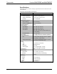
Crestron CHV-TSTAT and CHV-THSTAT Thermostats Specifications The following table provides a summary of specifications for the CHV-TSTAT and CHV-THSTAT. CHV-TSTAT and CHV-THSTAT Specifications SPECIFICATION DETAILS Measurement Range Indoor Temperature 0° to 110° F (-18° to 43° C) Outdoor Temperature -40º to 170º F (-40º to 77º C) 1 1 Humidity 0% to 100% RH Temperature Tolerance Over Full Range ±1º F (±0.5º C) At Room Temperatures ±1º F (+0.1/0.
Crestron CHV-TSTAT and CHV-THSTAT Thermostats CHV-TSTAT and CHV-THSTAT Specifications (Continued) SPECIFICATION DETAILS Available Accessories 1. 2. 3.
Crestron CHV-TSTAT and CHV-THSTAT Thermostats CHV-TSTAT and CHV-THSTAT Overall Dimensions (Front View) 5.00 in (127 mm) 1 MODE 2 VIEW 3 4 3.75 in (96 mm) 5 CHV-TSTAT and CHV-THSTAT Overall Dimensions (Side and Rear Views) 3.27 in 1.04 in (84 mm) (27 mm) 6 • Thermostats: CHV-TSTAT and CHV-THSTAT Operations and Installation Guide – DOC.
Crestron CHV-TSTAT and CHV-THSTAT Thermostats CHV-TSTAT and CHV-THSTAT Backplate (Front Cover Removed) 6 7 9 8 24V Y Z G HUM RHU RSR RSR RS1 RS2 24(C) 24(R) TOP RH RC G Y/Y1 Y2 O B W/W1 W2 NETWORK 6 Connectors, Controls & Indicators # CONNECTORS, CONTROLS & INDICATORS 1 MODE Button Accesses user controls (system mode, fan mode, humidifier, Crestron system, and global update) 2 VIEW Button Accesses humidity reading*, outdoor temperature reading*, system messages and remote functions 3 ▲
Crestron CHV-TSTAT and CHV-THSTAT Thermostats Connectors, Controls & Indicators (Continued) # CONNECTORS, CONTROLS & INDICATORS 6 Control Connections (System Dependent) DESCRIPTION (2) 9-position terminal blocks HUM: Energized to RHU during humidity call RHU: Reference for humidifier RH: Reference Heat, used for calls to heating system RC: Reference Cool, used for calls to cooling system G: Fan, energized to RC during fan call Y/Y1: Compressor (stage one), energized to RC when compressor (o
Crestron CHV-TSTAT and CHV-THSTAT Thermostats Setup Network Wiring When wiring the Cresnet network, consider the following: • Use Crestron Certified Wire. • Use Crestron power supplies for Crestron equipment. • Provide sufficient power to the system. CAUTION: Insufficient power can lead to unpredictable results or damage to the equipment. Use the Crestron Power Calculator to help calculate how much power is needed for the system (www.crestron.com/calculators).
Crestron CHV-TSTAT and CHV-THSTAT Thermostats System Connections NOTE: Installers should have a strong working knowledge of HVAC systems.
Crestron CHV-TSTAT and CHV-THSTAT Thermostats Wiring Diagrams The wiring diagrams that follow show connections for the CHV-TSTAT and CHV-THSTAT. The heating or cooling system can supply power to the thermostat, or a separate transformer can supply it. In many installations, spare conductors are available to supply 24 Vac to the thermostat, using the C (24 Vac common) connection on the HVAC equipment.
Crestron CHV-TSTAT and CHV-THSTAT Thermostats Separately Powered Two Wire Heat Systems (Powered by an Independent Transformer) Independent Transformer Connection – P4 Jumper Connects Pins 2 and 3 1-Stage Heat Only Systems 1-Stage Heat Only System Powered – P4 Jumper Connects Pins 1 and 2 12 • Thermostats: CHV-TSTAT and CHV-THSTAT Operations and Installation Guide – DOC.
Crestron CHV-TSTAT and CHV-THSTAT Thermostats 1-Stage Heat with Fan Control Systems 1-Stage Heat with Fan Control – P4 Connects Pins 1 and 2 – Additional Jumper Connects RH to RC 1-Stage Cool Only Systems 1-Stage Cool Only – P4 Jumper Connects Pins 3 and 4 Operations and Installation Guide – DOC.
Crestron CHV-TSTAT and CHV-THSTAT Thermostats 1-Stage Heat/Cool with Integrated Control Unit Systems 1-Stage Heat/Cool with Integrated Control Unit – P4 Jumper Connects Pins 1 and 2 – Additional Jumper RH to RC 14 • Thermostats: CHV-TSTAT and CHV-THSTAT Operations and Installation Guide – DOC.
Crestron CHV-TSTAT and CHV-THSTAT Thermostats 1-Stage Heat/Cool with Separate Systems 1-Stage Heat/Cool with Separate Systems – Heating System Powered – P4 Jumper Connects Pins 1 and 2 Operations and Installation Guide – DOC.
Crestron CHV-TSTAT and CHV-THSTAT Thermostats 1-Stage Heat Pump Systems 1-Stage Heat Pump – P4 Jumper Connects Pins 3 and 4– Additional Jumper RH to RC 16 • Thermostats: CHV-TSTAT and CHV-THSTAT Operations and Installation Guide – DOC.
Crestron CHV-TSTAT and CHV-THSTAT Thermostats 2-Stage Heat Pump Systems 2-Stage Heat Pump System – P4 Jumper Connects Pins 3 and 4 – Additional Jumper RH to RC Operations and Installation Guide – DOC.
Crestron CHV-TSTAT and CHV-THSTAT Thermostats Slab 1, Slab 2, and Slab 3 (Floor Warming and/or Space Heating) Systems Slab 1, Slab 2, and Slab 3 Systems (Floor Warming and/or Space Heating) – P4 Jumper Connects Pins 1 and 2 18 • Thermostats: CHV-TSTAT and CHV-THSTAT Operations and Installation Guide – DOC.
Crestron CHV-TSTAT and CHV-THSTAT Thermostats Slab 4A 2-Stage Heat/1-Stage Cool Systems and Slab 5A Floor Warming with 1-Stage Space Heat/Cool Systems Heat/Cool Style Connections Slab 4A – P4 Jumper Connects Pins 1 and 2 – Jumper Connects RH to RC Operations and Installation Guide – DOC.
Crestron CHV-TSTAT and CHV-THSTAT Thermostats Slab 4B 2-Stage Heat/1-Stage Cool System and Slab 5B 1-Stage Heat/Cool with Floor Warming Systems Heat Pump Style Connections Slab 4B – P4 Jumper Connects Pins 3 and 4 – Additional Jumper Connects RH to RC 20 • Thermostats: CHV-TSTAT and CHV-THSTAT Operations and Installation Guide – DOC.
Crestron CHV-TSTAT and CHV-THSTAT Thermostats General Humidifier Connections General Humidifier Connections Operations and Installation Guide – DOC.
Crestron CHV-TSTAT and CHV-THSTAT Thermostats Installation The location of the thermostat can affect its performance and efficiency. Install the thermostat away from direct sunlight, drafts, doorways, skylights, and windows. Also make sure the thermostat is conveniently located for programming, and do not mount on an exterior wall. The thermostats may be mounted directly to drywall or to a 1-gang box. Thermostats and sensors are mounted 60 inches (~1.
Crestron CHV-TSTAT and CHV-THSTAT Thermostats Installing the CHV-TSTAT and CHV-THSTAT in a Horizontally Mounted 1-Gang Electrical Box NOTE: Install insulation (not supplied) in the 1-gang electrical box to prevent inaccurate readings. Stud 1-gang electrical box (not provided) Panhea d 6/32 x 1 in Installing the CHV-TSTAT and CHV-THSTAT Directly On the Wall Wall Anchors (not provided) Mounting Screws (not provided) Operations and Installation Guide – DOC.
Crestron CHV-TSTAT and CHV-THSTAT Thermostats Thermostat Setup Setup Procedure After the thermostat is installed, it is necessary to set it up for a particular heating/cooling system. There are nine types of heating and cooling systems. The available choices displayed on the setup screens depend on the type of system selected. Follow these directions to access the setup screens. 1. Press and hold the MODE and VIEW buttons simultaneously for 5 seconds to access the setup menus. 2.
Crestron CHV-TSTAT and CHV-THSTAT Thermostats NOTE: When the Reverse SMODE Dir (reverse system mode direction) selection is set to Yes on the “SCRN OPTIONS” (screen options) setup screen, the arrow keys (▲ ▼) can be used to select system mode functions in both directions. NOTE: If an out of range setpoint is entered, it is ignored. NOTE: The screen options selected during setup are seen when the View key is pressed in normal operation.
Crestron CHV-TSTAT and CHV-THSTAT Thermostats 3. Slab Systems Definitions Slab heating works from the ground up. The heating components are installed below the floor or are embedded in a concrete slab. Heat radiates from the floor to warm the space above. The CHV-TSTAT and CHV-THSTAT support seven variations of slab heat systems. SLAB 1: Floor warming only. Operates the slab heat to maintain a particular slab temperature. System mode is enabled/disabled with Floor Warming Heat and OFF inputs.
Crestron CHV-TSTAT and CHV-THSTAT Thermostats Heat/Cool, 1 or 2 Stages, Forced Air or Radiant Press and hold the MODE and VIEW buttons simultaneously for 5 seconds to enter setup. SETUP: SYSTEM SETUP: SYSTEM Heat Sys Type: # Heat Stages: # Cool Stages: Radiant / F. Air: Heat Sys Type: H/C H/C 2 2 F.Air SEPARATE HEAT AND COOL Press # Heat Stages: One or two heat stages. # Cool Stages: One or two cool stages. Radiat /F. Air: Radiant or Forced Air Heat.
Crestron CHV-TSTAT and CHV-THSTAT Thermostats SETUP: HUMIDITY OPTIONS SETUP: HUM OPTS Show Hum Mode Pg: Show Hum View Pg: Cold Weather Comp: Y Y N SYSTEM ENABLE/DISABLE PAGE SETUP: HUM OPTS INVERTED HUM RELAY LOGIC HUM ABOVE SP = ENERGIZED Invert Hum Output Call FAN in HUM: Press Y N To Continue Show Hum Mode Pg and Show Hum View Pg: Select Y to show humidity page in normal operation. Cold Weather Comp: Modifies the humidifier output to prevent condensation on windows.
Crestron CHV-TSTAT and CHV-THSTAT Thermostats SETUP: DISPLAY OPTIONS SETUP: DISP OPTIONS Temperature Units: F Temp Disp Offset: 00 Dual Setpoint Auto: Y Main Scn Lwr Obj: HM Use 0.5 Deg C Step: Y Press To Continue Temperature Units: Display temperature units in (F) Fahrenheit or (C) Celsius. Temp Disp Offset: Select -6° – +6° F. Allows the user to adjust the displayed and regulated temperature. Dual Setpoint Auto: Enables 2-point auto mode.
Crestron CHV-TSTAT and CHV-THSTAT Thermostats NOTE: REMOTE 1 and REMOTE 2 options do not appear on this screen if these sensors are not connected. NOTE: Thermostat auto-detects connected remote sensors. SETUP: HUMIDITY SENSORS TRIM: Select -9 – +9. Allows the user to calibrate the INTERNAL, REMOTE 1 and REMOTE 2 humidity sensors to match % RH values obtained by other equipment. The values here are based on a logarithmic index and are not to be interpreted as units of measurement.
Crestron CHV-TSTAT and CHV-THSTAT Thermostats Heat Pump, 1 or 2 Stages, Aux Heat or Dual Fuel Press and hold the MODE and VIEW buttons simultaneously for 5 seconds to enter the setup mode. SETUP: SYSTEM SETUP: SYSTEM HPump Heat Sys Type: 2 # of Stages: HP/Aux HP/AUX or DF: HEATPUMP SYSTEM Press To Continue Heat Sys Type: HPump # of Stages: Select 1 or 2 stages. HP/AUX or DF: Dual fuel runs either the heat pump or the aux output, depending on outdoor temperature.
Crestron CHV-TSTAT and CHV-THSTAT Thermostats SETUP: HUMIDITY OPTIONS SETUP: HUM OPTS Show Hum Mode Pg: Show Hum View Pg: Cold Weather Comp: Y Y N SYSTEM ENABLE/DISABLE PAGE SETUP: HUM OPTS INVERTED HUM RELAY LOGIC HUM ABOVE SP = ENERGIZED Invert Hum Output Call FAN in HUM: Press Y N To Continue Show Hum Mode Pg and Show Hum View Pg: Select Y to show humidity page in normal operation. Cold Weather Comp: Modifies the humidifier output to prevent condensation on the windows.
Crestron CHV-TSTAT and CHV-THSTAT Thermostats SETUP: DISPLAY OPTIONS SETUP: DISP OPTIONS Temperature Units: F Temp Disp Offset: 00 Dual Setpoint Auto: Y Main Scn Lwr Obj: HM Use 0.5 Deg C Step: Y Press To Continue Temperature Units: Display temperature units in (F) Fahrenheit or (C) Celsius. Temp Disp Offset: Select -6° – +6° F. Allows the user to adjust the displayed and regulated temperature. Dual Setpoint Auto: Enables 2-point auto mode.
Crestron CHV-TSTAT and CHV-THSTAT Thermostats SETUP: HUMIDITY SENSORS TRIM: Select -9 – +9. Allows the user to calibrate the INTERNAL, REMOTE 1 and REMOTE 2 humidity sensors to match % RH values obtained by other equipment. The values here are based on a logarithmic index and are not to be interpreted as units of measurement. SETUP: H-SENSORS TRIM % RH INTERNAL: -5 45 REMOTE 1: 0 50 REMOTE 2: 0 30 NOTE: For best results, calibration should be performed when RH is 40% or higher.
Crestron CHV-TSTAT and CHV-THSTAT Thermostats Slab 1 – Floor Warming Only Press and hold the MODE and VIEW buttons simultaneously for 5 seconds to enter the setup mode. SETUP: SYSTEM SETUP: SYSTEM SLAB 1 Heat Sys Type: 6 Slab Reg: FLOOR WARMING ONLY (W1) Press Heat Sys Type: SLAB 1 Slab Regulation: Select 1 – 6. 1 = Narrow temperature regulation 6 = Wide temperature regulation NOTE: Slab mode 1 requires a slab remote sensor (CHV-RSS, sold separately).
Crestron CHV-TSTAT and CHV-THSTAT Thermostats SETUP: DEVICE OPTIONS SETUP: DEVICE OPTS Network ID: 2A LCD Contrast 5 CHV-THSTAT [v2.0, #D8000000] Press Network ID: Valid entries are 03 to FE in hex to match the network ID set for the thermostat in Crestron Studio or SIMPL Windows. LCD Contrast: Select 1 – 10 to lighten or darken screen. This screen displays model number, firmware version and TSID.
Crestron CHV-TSTAT and CHV-THSTAT Thermostats SETUP: OTHER SETTINGS SETUP: OTHER SETTINGS No applicable settings. NO APPLICABLE SETTINGS Press To Continue SETUP: SENSORS SETUP: SENSORS SENSOR >TEMP HUM INTERNAL: USE OMIT REMOTE 1: SLAB DETECTED: 1 x T REMOTE 2: Press To Continue INTERNAL: Choose USE or OMIT. Choose USE to permit temperature averaging. NOTE: Sensor temperature and humidity can be output to network even if OMIT is chosen.
Crestron CHV-TSTAT and CHV-THSTAT Thermostats SETUP: SENSOR DEBUGGING SETUP: SENSOR DBG IST/ AVG F: 75 LOW/HI F: 74 COMM ERR: 1 RUN 100% Press 74 75 1 76 75 0 76 76 0 62 62 62 45 45 45 To Continue Press VIEW to run or stop sensor debugging. A completion progress bar indicates debugging status. IST / AVG F: Displays the instantaneous and average temperature (F) for RS1, followed by the instantaneous and average temperature (F) for RS2.
Crestron CHV-TSTAT and CHV-THSTAT Thermostats Slab 2 – 1-Stage Space Heat with Slab Maximum Press and hold the MODE and VIEW buttons simultaneously for 5 seconds to enter the setup mode. SETUP: SYSTEM SETUP: SYSTEM SLAB 2 Heat Sys Type: 122o Slab MAX T: Slab MAX T: Select 39° – 122° F (39° – 50° C). Used to prevent the floor from becoming too hot on long heat calls. NOTE: Slab mode 2 requires an air temperature source and a slab remote sensor (CHV-RSS, sold separately).
Crestron CHV-TSTAT and CHV-THSTAT Thermostats SETUP: DEVICE OPTIONS SETUP: DEVICE OPTS Network ID: 2A LCD Contrast 5 CHV-THSTAT [v2.0, #D8000000] Press Network ID: Valid entries are 03 to FE in hex to match the network ID set for the thermostat in Crestron Studio or SIMPL Windows. LCD Contrast: Select 1 – 10 to lighten or darken screen. This screen displays model number, firmware version and TSID.
Crestron CHV-TSTAT and CHV-THSTAT Thermostats SETUP: OTHER SETTINGS SETUP: OTHER SETTINGS No applicable settings. NO APPLICABLE SETTINGS Press To Continue SETUP: SENSORS SETUP: SENSORS SENSOR >TEMP HUM INTERNAL: USE OMIT REMOTE 1: SLAB DETECTED: 1 x T REMOTE 2: Press INTERNAL: Choose USE or OMIT. Choose USE to permit temperature averaging. NOTE: Sensor temperature and humidity can be output to network even if OMIT is chosen.
Crestron CHV-TSTAT and CHV-THSTAT Thermostats SETUP: SENSOR DEBUGGING SETUP: SENSOR DBG IST/ AVG F: 75 LOW/HI F: 74 COMM ERR: 1 RUN 100% 74 75 1 76 75 0 62 62 62 45 45 45 Press 76 76 0 To Continue Press VIEW to run or stop sensor debugging. A completion progress bar indicates debugging status. IST / AVG F: Displays the instantaneous and average temperature (F) for RS1, followed by the instantaneous and average temperature (F) for RS2.
Crestron CHV-TSTAT and CHV-THSTAT Thermostats Slab 3 – 1-Stage Heat with Slab Minimum/Maximum Press and hold the MODE and VIEW buttons simultaneously for 5 seconds to enter setup mode. SETUP: SYSTEM Heat Sys Type: SLAB 3 SETUP: SYSTEM Heat Sys Type: SLAB 3 Slab MAX T: 122o Slab Reg: 6 Slab MAX T: Select 39° – 122° F (39° – 50° C). Used to prevent the floor from becoming too hot on long heat calls. Slab Reg: Select 1 – 6.
Crestron CHV-TSTAT and CHV-THSTAT Thermostats SETUP: DEVICE OPTIONS SETUP: DEVICE OPTS Network ID: 2A LCD Contrast 5 CHV-THSTAT [v2.0, #D8000000] Press Network ID: Valid entries are 03 to FE in hex to match the network ID set for the thermostat in Crestron Studio or SIMPL Windows. LCD Contrast: Select 1 – 10 to lighten or darken screen. This screen displays model number, firmware version and TSID.
Crestron CHV-TSTAT and CHV-THSTAT Thermostats SETUP: OTHER SETTINGS SETUP: OTHER SETTINGS No applicable settings. NO APPLICABLE SETTINGS Press To Continue SETUP: SENSORS SETUP: SENSORS SENSOR >TEMP HUM INTERNAL: USE OMIT REMOTE 1: SLAB DETECTED: 1 x T REMOTE 2: Press INTERNAL: Choose USE or OMIT. Choose USE to permit temperature averaging. NOTE: Sensor temperature and humidity can be output to network even if OMIT is chosen.
Crestron CHV-TSTAT and CHV-THSTAT Thermostats SETUP: SENSOR DEBUGGING SETUP: SENSOR DBG IST/ AVG F: 75 LOW/HI F: 74 COMM ERR: 1 RUN 100% 74 75 1 76 75 0 62 62 62 45 45 45 Press 76 76 0 To Continue Press VIEW to run or stop sensor debugging. A completion progress bar indicates debugging status. IST / AVG F: Displays the instantaneous and average temperature (F) for RS1, followed by the instantaneous and average temperature (F) for RS2.
Crestron CHV-TSTAT and CHV-THSTAT Thermostats Slab 4A – 2-Stage Heat/1-Stage Cool with Slab Maximum Press and hold the MODE and VIEW buttons simultaneously for 5 seconds to enter setup mode. SETUP: SYSTEM Heat System Type: SLAB 4A SETUP: SYSTEM SLAB 4A Heat Sys Type: 122o Slab MAX T: Slab MAX T: Select 39° – 122° F (39° – 50° C). Used to prevent the floor from becoming too hot on long heat calls.
Crestron CHV-TSTAT and CHV-THSTAT Thermostats SETUP: DEVICE OPTIONS SETUP: DEVICE OPTS Network ID: 2A LCD Contrast 5 CHV-THSTAT [v2.0, #D8000000] Press Network ID: Valid entries are 03 to FE in hex to match the network ID set for the thermostat in Crestron Studio or SIMPL Windows. LCD Contrast: Select 1 – 10 to lighten or darken screen. This screen displays model number, firmware version and TSID.
Crestron CHV-TSTAT and CHV-THSTAT Thermostats SETUP: OTHER SETTINGS Wide Range Cool: Extends cool setpoint to full auto range of 38º – 99º F (3º – 37º C). SETUP: OTHER SETTINGS N N 20 N Wide Range Cool: Run Fan in Ht Calls: Auto DdBand Deg: Disable Auto Mode: Run Fan in Ht Calls: If the heating system requires fan control, select Y. EXTENDED COOL SETPOINT RANGE 38-99F (3-37C) Press NOTE: Most heating systems run the fan automatically. Auto Mode Dead Band: Select 2 – 6.
Crestron CHV-TSTAT and CHV-THSTAT Thermostats SETUP: SENSOR DEBUGGING SETUP: SENSOR DBG IST/ AVG F: 75 LOW/HI F: 74 COMM ERR: 1 RUN 100% Press 74 75 1 76 75 0 76 76 0 62 62 62 45 45 45 To Continue Press VIEW to run or stop sensor debugging. A completion progress bar indicates debugging status. IST / AVG F: Displays the instantaneous and average temperature (F) for RS1, followed by the instantaneous and average temperature (F) for RS2.
Crestron CHV-TSTAT and CHV-THSTAT Thermostats Slab 4B – 2-Stage Heat/1-Stage Cool with Slab Maximum (Heat Pump) Press and hold the MODE and VIEW buttons simultaneously for 5 seconds to enter setup mode. SETUP: SYSTEM SETUP: SYSTEM Heat Sys Type: SLAB 4B Slab MAX T: 122o HP/AUX or DF: HP/Aux 2 STG SPACE HEAT - 1 STG COOL WITH SLAB MAX (HP) SLAB = W1, HT/CL = Y1/O/G Press To Continue Heat Sys Type: SLAB 4B Slab MAX T: Select 39° – 122° F (39° – 50° C).
Crestron CHV-TSTAT and CHV-THSTAT Thermostats SETUP: HUMIDITY OPTIONS SETUP: HUM OPTS Show Hum Mode Pg: Show Hum View Pg: Cold Weather Comp: Y Y N SYSTEM ENABLE/DISABLE PAGE SETUP: HUM OPTS INVERTED HUM RELAY LOGIC HUM ABOVE SP = ENERGIZED Invert Hum Output Call FAN in HUM: Press Y N To Continue Show Hum Mode Pg and Show Hum View Pg: Select Y to show humidity page in normal operation. Cold Weather Comp: Modifies the humidifier output to prevent condensation on the windows.
Crestron CHV-TSTAT and CHV-THSTAT Thermostats SETUP: DISPLAY OPTIONS SETUP: DISP OPTIONS Temperature Units: F Temp Disp Offset: 00 Dual Setpoint Auto: Y Main Scn Lwr Obj: HM Use 0.5 Deg C Step: Y Press To Continue Temperature Units: Display temperature units in (F) Fahrenheit or (C) Celsius. Temp Disp Offset: Select -6° – +6° F. Allows the user to adjust the displayed and regulated temperature. Dual Setpoint Auto: Enables 2-point auto mode.
Crestron CHV-TSTAT and CHV-THSTAT Thermostats SETUP: HUMIDITY SENSORS TRIM: Select -9 – +9. Allows the user to calibrate the INTERNAL, REMOTE 1 and REMOTE 2 humidity sensors to match % RH values obtained by other equipment. The values here are based on a logarithmic index and are not to be interpreted as units of measurement. SETUP: H-SENSORS TRIM % RH INTERNAL: -5 45 REMOTE 1: 0 50 REMOTE 2: 0 30 NOTE: For best results, calibration should be performed when RH is 40% or higher.
Crestron CHV-TSTAT and CHV-THSTAT Thermostats Slab 5A – 1-Stage Heat/Cool with Floor Warming Press and hold the MODE and VIEW buttons simultaneously for 5 seconds to enter setup mode. SETUP: SYSTEM Heat System Type: SLAB 5A SETUP: SYSTEM SLAB 5A Heat Sys Type: 2 Slab Reg: Slab Regulation: Select 1 – 6.
Crestron CHV-TSTAT and CHV-THSTAT Thermostats SETUP: DEVICE OPTIONS SETUP: DEVICE OPTS Network ID: 2A LCD Contrast 5 CHV-THSTAT [v2.0, #D8000000] Press Network ID: Valid entries are 03 to FE in hex to match the network ID set for the thermostat in Crestron Studio or SIMPL Windows. LCD Contrast: Select 1 – 10 to lighten or darken screen. This screen displays model number, firmware version and TSID.
Crestron CHV-TSTAT and CHV-THSTAT Thermostats SETUP: OTHER SETTINGS SETUP: OTHER SETTINGS N N 20 N Wide Range Cool: Run Fan in Ht Calls: Auto DdBand Deg: Disable Auto Mode: EXTENDED COOL SETPOINT RANGE 38-99F (3-37C) Press To Continue Wide Range Cool: Extends cool setpoint to full auto range of 38º – 99º F (3º – 37º C). Run Fan in Ht Calls: If the heating system requires fan control, select Y. NOTE: Most heating systems run the fan automatically. Auto DdBand Deg: Select 2 – 6.
Crestron CHV-TSTAT and CHV-THSTAT Thermostats SETUP: SENSOR DEBUGGING SETUP: SENSOR DBG IST/ AVG F: 75 LOW/HI F: 74 COMM ERR: 1 RUN 100% Press 74 75 1 76 75 0 76 76 0 62 62 62 45 45 45 To Continue Press VIEW to run or stop sensor debugging. A completion progress bar indicates debugging status. IST / AVG F: Displays the instantaneous and average temperature (F) for RS1, followed by the instantaneous and average temperature (F) for RS2.
Crestron CHV-TSTAT and CHV-THSTAT Thermostats Slab 5B – 1-Stage Heat/Cool with Floor Warming (Heat Pump) Press and hold the MODE and VIEW buttons simultaneously for 5 seconds to enter setup mode. SETUP: SYSTEM SETUP: SYSTEM Heat Sys Type: SLAB 5B Slab Reg: 6 HP/AUX or DF: HP/Aux 1 STG SPACE HEAT - COOL W/ FLOOR WARMING (HEATPUMP) SLAB=W1 HT/CL=Y1/O/G Press To Continue Heat System Type: SLAB 5B Slab Reg: Select 1 – 6.
Crestron CHV-TSTAT and CHV-THSTAT Thermostats SETUP: HUMIDITY OPTIONS SETUP: HUM OPTS Show Hum Mode Pg: Show Hum View Pg: Cold Weather Comp: Y Y N SYSTEM ENABLE/DISABLE PAGE SETUP: HUM OPTS INVERTED HUM RELAY LOGIC HUM ABOVE SP = ENERGIZED Invert Hum Output Call FAN in HUM: Press Y N To Continue Show Hum Mode Pg and Show Hum View Pg: Select Y to show humidity page in normal operation. Cold Weather Compensation: Modifies the humidifier output to prevent condensation on the windows.
Crestron CHV-TSTAT and CHV-THSTAT Thermostats SETUP: DISPLAY OPTIONS SETUP: DISP OPTIONS Temperature Units: F Temp Disp Offset: 00 Dual Setpoint Auto: Y Main Scn Lwr Obj: HM Use 0.5 Deg C Step: Y Press To Continue Temperature Units: Display temperature units in (F) Fahrenheit or (C) Celsius. Temp Disp Offset: (-6° – +6° F) Allows the user to adjust the displayed and regulated temperature. Dual Setpoint Auto: Enables 2-point auto mode.
Crestron CHV-TSTAT and CHV-THSTAT Thermostats SETUP: HUMIDITY SENSORS TRIM: Select -9 – +9. Allows the user to calibrate the INTERNAL, REMOTE 1 and REMOTE 2 humidity sensors to match % RH values obtained by other equipment. The values here are based on a logarithmic index and are not to be interpreted as units of measurement. SETUP: H-SENSORS TRIM % RH INTERNAL: -5 45 REMOTE 1: 0 50 REMOTE 2: 0 30 NOTE: For best results, calibration should be performed when RH is 40% or higher.
Crestron CHV-TSTAT and CHV-THSTAT Thermostats Thermostat Operation The main screen displays the current temperature, system mode, fan mode, relative humidity and setpoint temperatures.
Crestron CHV-TSTAT and CHV-THSTAT Thermostats View Button Menus Pressing the VIEW button allows the user to access the following screens: NOTE: If enabled, the VIEW button also allows access to the remote button function screens. When part of a Cresnet system, the up ▲ and down ▼ arrow buttons can be used to enable other functions (i.e., lighting control, alarm system, etc). “Humidity” Screen VIEW 30 % 24 % Humidity MODE Press the VIEW button to display the “Humidity” screen.
Crestron CHV-TSTAT and CHV-THSTAT Thermostats Mode Button Menus Heat/Cool, Heat Pump and Slab 4 Systems Pressing the MODE button allows the user to access the following screens when the thermostat is configured for Heat/Cool, Heat Pump and Slab 4 Systems. “System Mode” Screen MODE System Mode VIEW HEAT COOL AUTO OFF AUX HEAT ONLY The “System Mode” screen appears when the MODE button is initially pressed. Use the up ▲and down ▼arrow buttons to select HEAT, COOL, AUTO, OFF or AUX HEAT ONLY.
Crestron CHV-TSTAT and CHV-THSTAT Thermostats “Crestron System” Screen VIEW Crestron Sys ONLINE HOLD MODE Pressing the MODE button again displays the “Crestron Sys” (Crestron system) screen. Use the up ▲and down▼arrow buttons to select ONLINE or HOLD. • ONLINE: Data flows both ways, to and from the thermostat, enabling adjustment from a remote location.
Crestron CHV-TSTAT and CHV-THSTAT Thermostats Slab 5 Systems Pressing the MODE button allows the user to access the following screens when the thermostat is configured for Slab 5 Systems. “Floor Warming” Screen VIEW Floor Warming MODE 76 0 F 82 0 F The “Floor Warming” screen appears when the MODE button is initially pressed. This screen displays current floor warming temperature and setpoint.
Crestron CHV-TSTAT and CHV-THSTAT Thermostats “ Humidifier” Screen VIEW Humidifier MODE ENABLED DISABLED Pressing the MODE button again displays the “Humidifier” screen. NOTE: This page only appears if enabled in the “HUM OPTS” setup screen. NOTE: CHV-TSTAT requires additional remote humidity sensor (CHV-RTHS, sold separately). Use the up ▲and down ▼arrow buttons to select ENABLED or DISABLED.
Crestron CHV-TSTAT and CHV-THSTAT Thermostats Slab 1 and Slab 2 Systems Pressing the MODE button allows the user to access the following screens when the thermostat is configured for Slab 1 and Slab 2 systems. “Slab System Mode” Screen VIEW Slab System Mode HEAT OFF MODE The “Slab System Mode” screen appears when the MODE button is initially pressed. Use the up ▲and down▼arrow buttons to select HEAT or OFF.
Crestron CHV-TSTAT and CHV-THSTAT Thermostats “Global Update” Screen Global Update SEND VIEW MODE Pressing the MODE button again displays the “Global Update” screen. This feature allows a single thermostat location to update the current temperature settings to all other thermostats on the system, provided that this function has been defined in the Crestron program. Press the down▼ button to send the update. Pressing the MODE button again displays the main screen.
Crestron CHV-TSTAT and CHV-THSTAT Thermostats “ Humidifier” Screen VIEW Humidifier MODE ENABLED DISABLED Pressing the MODE button again displays the “Humidifier” screen. NOTE: This page only appears if enabled in the “HUM OPTS” setup screen. NOTE: CHV-TSTAT requires additional remote humidity sensor (CHV-RTHS, sold separately). Use the up ▲and down ▼arrow buttons to select ENABLED or DISABLED.
Crestron CHV-TSTAT and CHV-THSTAT Thermostats Uploading and Upgrading Crestron recommends using the latest programming software and that each device contains the latest firmware to take advantage of the most recently released features. However, before attempting to upload or upgrade it is necessary to establish communication. Once communication has been established, files (for example, programs or firmware) can be transferred to the control system (or device).
Crestron CHV-TSTAT and CHV-THSTAT Thermostats Programs and Firmware Program or firmware files may be distributed from programmers to installers or from Crestron to dealers. Firmware upgrades are available from the Crestron Web site as new features are developed after product releases. One has the option to upload programs via the programming software or to upload and upgrade via the Crestron Toolbox.
Crestron CHV-TSTAT and CHV-THSTAT Thermostats Problem Solving Troubleshooting The table below provides corrective action for possible trouble situations. If further assistance is required, please contact a Crestron customer service representative.
Crestron CHV-TSTAT and CHV-THSTAT Thermostats CHV-TSTAT/CHV-THSTAT Troubleshooting (Continued) TROUBLE POSSIBLE CAUSE(S) CORRECTIVE ACTION Wide temperature variance in singlesetpoint auto mode Auto deadband setting too high Adjust auto deadband setting in setup Heating/Cooling not operating in singlesetpoint auto mode 20-minute system toggling lockout Adjust auto deadband and anticipator settings for smoother operation Displays Error Message and equipment not operating Temperature sensors are d
Crestron CHV-TSTAT and CHV-THSTAT Thermostats Control System Error Log Message Formats When a remote sensor that has been designated as USE, SLAB, or OD in the Setup Sensors screen (refer to “Thermostat Setup”, which begins on page 24) generates an error, a message is sent to the error log. Retrieve this message using the System Info tool in Crestron Toolbox: 1. Using Crestron Toolbox, select Tools|System Info. 2. Select the control system from the address bar and examine the Error Log.
Crestron CHV-TSTAT and CHV-THSTAT Thermostats Local Error Messages When a critical sensor fails and prevents the safe or intended operation of the HVAC equipment, an error message flashes on the main screen. This error message appears as a text message under the line that normally reads ON LINE and VIEW MSG. The thermostat messages are shown as follows in descending priority.
Crestron CHV-TSTAT and CHV-THSTAT Thermostats chained must be added together to determine the Cresnet power usage of the entire chain. If the unit is home-run from a Crestron system power supply network port, the Cresnet power usage of that unit is the Cresnet power usage of the entire run. The wire gauge and the Cresnet power usage of the run should be used in the following equation to calculate the cable length value on the equation’s left side.
Crestron CHV-TSTAT and CHV-THSTAT Thermostats Future Updates As Crestron improves functions, adds new features and extends the capabilities of the CHV-TSTAT/CHV-THSTAT, additional information may be made available as manual updates. These updates are solely electronic and serve as intermediary supplements prior to the release of a complete technical documentation revision. Check the Crestron Web site periodically for manual update availability and its relevance.
Crestron CHV-TSTAT and CHV-THSTAT Thermostats Appendix A: About Heat Pumps A heat pump extracts available heat from one area and transfers it to another. Even cold air contains some heat, and heat pumps can extract heat from the outside air on a cold day and transfer it indoors to maintain a comfortable temperature. A heat pump also works in reverse during the summer, extracting heat from indoors and transferring it outdoors.
Crestron CHV-TSTAT and CHV-THSTAT Thermostats Glossary Anticipators Used to anticipate the drop or rise in temperature and energize the appropriate system before reaching the setpoint. Auto Dead Band Degree (Auto DdBand Deg) Sets the minimum separation in auto mode between the heat and cool setpoints, or the changeover band in 1-point auto mode.
Crestron CHV-TSTAT and CHV-THSTAT Thermostats Heat Pump A unit that both cools and heats. A heat pump system can be either a split system or a packaged system. A heat pump can be used in conjunction with a gas/oil/LP furnace (using the furnace instead of electric resistance heat when temperatures fall below about 35º F). Humidity The total amount of moisture in air. Relative humidity (RH) is the amount of moisture in air, relative to its total capability based upon its temperature (dewpoint).
Crestron CHV-TSTAT and CHV-THSTAT Thermostats Return and Warranty Policies Merchandise Returns / Repair Service 1. No merchandise may be returned for credit, exchange or service without prior authorization from Crestron. To obtain warranty service for Crestron products, contact an authorized Crestron dealer. Only authorized Crestron dealers may contact the factory and request an RMA (Return Merchandise Authorization) number.
Crestron CHV-TSTAT and CHV-THSTAT Thermostats This page is intentionally left blank. 84 • Thermostats: CHV-TSTAT and CHV-THSTAT Operations and Installation Guide – DOC.
Crestron CHV-TSTAT and CHV-THSTAT Thermostats This page is intentionally left blank. Operations and Installation Guide – DOC.
Crestron Electronics, Inc. 15 Volvo Drive Rockleigh, NJ 07647 Tel: 888.CRESTRON Fax: 201.767.7576 www.crestron.com Operations & Installation Guide – DOC. 8163E (2002184) 02.13 Specifications subject to change without notice.