
User Guide

Terminal Block & Module Crestron CLT- & CLX-1DIM4
5. Grounding terminal blocks are available in the
cabinet for termination of ground wires. Tighten
to 35 in-lbs. (14 – 10 AWG), 40 in-lbs.
(8 AWG), or 45 in-lbs. (6 – 4 AWG).
NOTE: Unless otherwise indicated, the lighting system
specified in this guide is modular, requiring assembly in
the field by a licensed electrician, in accordance with all
national and local codes.
6. Test the circuit for electrical faults by turning on
the circuit breaker, checking that the breaker
does not trip, and that power is delivered to the
proper loads.
If you require a UL Listed panel, Crestron offers this
service through its UL Listed panel shop. This includes
complete in factory system configuration and assembly by
Crestron for an additional fee.
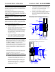
Wiring Diagram of the Terminal Block to the Feed and
Load(s)(Single-wide and Left Side Double-wide Enclosures)
Terminal Block Installation and Field
Wiring
TERMINAL
BLOCK
N OUT 2
GROUNDING
TERMINAL
BLOCK
GND
LEFT SIDE
WIRING LABEL
TO
LOAD(S)
AREA FOR
MODULE
LOCATION
LABEL
N OUT 3
N OUT 4
(FROM 15 OR 20 AMP
CIRCUIT BREAKER)
NEUTRAL
LINE
BYPASS
JUMPER
DIM 1
DIM 3
N IN
N OUT 1
DIM 4
DIM 2
LINE
120VAC 60 Hz
16A MAX
1 FEED
4 DIM
CLX-1DIM4
CRESTRON
NOTE: Both left-side and right-side adhesive wiring
labels are provided. The left-side labels are used in both
single and double-wide enclosures. The right-side labels
are only used in double-wide enclosures.
1. Remove the backing from the left or right
adhesive wiring label.
2. Apply the adhesive label by aligning the holes in
the label with the holes on the Crestron
Automation Enclosure where the terminal block
is to be mounted. The wiring label lies beneath
the terminal block as shown in the two wiring
diagrams on this page.
3. Use the two supplied self-tapping pan Phillips
screws (8B x ¼ length) to secure the terminal
block to the Crestron Automation Enclosure.
CAUTION: A bypass jumper is provided to allow
testing and to protect the module during installation.
When properly secured by five screws, the jumper on
the black and red section of the terminal block shorts
the LINE in to DIM out so that the circuit is
energized. Do not remove the bypass jumper until all
feed and load wiring has been completed, the circuit
has been tested for electrical faults, and the module
has been installed. Refer to “Module Installation” on
next page.
Furthermore, the jumper on the white section of the
terminal block ties the neutral in to the neutral outs.
This jumper should never be removed.
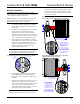
Wiring Diagram of the Terminal Block to the Feed and
Load(s) (Right Side Double-wide Enclosures)
NEUTRAL
(FROM 15
OR 20 AMP
CIRCUIT
BREAKER)
N OUT 4
N OUT 3
N OUT 2
N OUT 1
N IN
DIM 4
DIM 3
DIM 2
DIM 1
LINE
TERMINAL
BL
OC
K
AREA FOR
MODULE
LOCATION
LABEL
RIGHT SIDE
WIRIN
G
LABEL
TO
LOAD(S)
GROUNDING
TERMINAL
BLOCK
LINE
BYPASS
JUMPER
120VAC 60 Hz
16A MAX
GND
1 FEED
CLX-1DIM4
4 DIM
CRESTRON
NOTE: Use copper conductors only – rated 75°C
4. With the circuit breakers turned off, connect the
circuit feed (LINE and NEUTRAL) and
controlled circuit (LOAD) wires to the terminal
block per the markings provided on the wiring
label (as shown in the diagrams on this page).
Terminal blocks accept one 14 - 10 AWG wire.
Wires should be stripped to ½ inch. Tighten
terminal blocks to 9 in-lbs.
2 • Terminal Block & Module: CLT- & CLX-1DIM4 Installation Guide – DOC. 5987C