
User Guide
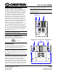

Crestron CLT- & CLX-1DIM4 Terminal Block & Module
Module Installation
CAUTION: Module contains electrostatic sensitive
devices (ESDs); unit must be handled from metal chassis
– do not touch PC board or components.
NOTE: Modules are to be installed after enclosure has
been completely wired. Refer to the terminal block
installation procedure on page 2 for details.
1. Use the four supplied self-tapping pan Phillips
screws (8B x ¼ length) to secure the module to
the enclosure.
2. As shown in the wiring diagrams (next column),
connect the wires from the module to the
terminal block. Each wire exits the module
directly in line with, and is the same color as, the
terminal to which it should be connected. Wires
are pre-stripped to ½ inch. Tighten to 9 in-lbs.
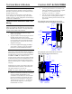
3. If the module is being installed above another
module within the enclosure, attach the supplied
module interconnect cable between the two
modules. The illustration below depicts the area
within a double-wide enclosure where the
corners of four modules meet.
NOTE: One wire on the module interconnect cable
may be a different color from the rest. The color has
no bearing on its orientation during installation.
Use Module Interconnect Cable to Wire Module to Module
MODULE
INTERCONNECT
CABLE ATTACHED
CONNECTION
NOT
MADE
4. Turn on the circuit breaker and verify that the
green PWR LED on the module lights, the
breaker does not trip, and power is delivered to
the loads.
5. Turn off the circuit breaker and remove the five-
position bypass jumper on the black and red
section of the terminal block. The bypass jumper
on the white section of the terminal block
remains installed. Refer to the figures in the next
column for a close-up of the jumpers.
NOTE: Before the five-position bypass jumper,
shown in the illustration, is removed, the Crestron
Professional Automation Computer (PAC2), which
provides control to the system, should be properly
connected and contain a valid program to provide
control of the module.
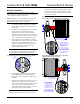
Wiring Diagram of the Terminal Block to the Module
(Single-wide and Left Side Double-wide Enclosures)
ENLARGEMENT DETAIL:
LOCATION OF FIVE-POSITION
BYPASS JUMPER ON
TERMINAL BLOCK AS
DESCRIBED IN STEP 5.
JUMPER ON BLACK AND
RED SECTION OF TERMINAL
BLOCK HAS BEEN REMOVED
AFTER LOOSENING SCREWS.
JUMPER ON WHITE SECTION
REMAINS INSTALLED.
JUMPER
ATTACH MODULE
INTERCONNECT CABLE
(DESCRIBED IN STEP 3)
WHITE
BLACK
RED
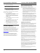
Wiring Diagram of the Terminal Block to the Module
(Right Side Double-wide Enclosures)
ATTACH MODULE
INTERCONNECT CABLE
(DESCRIBED IN STEP 3)
ENLARGEMENT DETAIL:
LOCATION OF FIVE-POSITION
BYPASS JUMPER ON
TERMINAL BLOCK AS
DESCRIBED IN STEP 5.
JUMPER ON WHITE SECTION
REMAINS INSTALLED.
JUMPER ON BLACK AND
RED SECTION OF TERMINAL
BLOCK HAS BEEN REMOVED
AFTER LOOSENING SCREWS.
JUMPER
WHITE
BLACK
RED
Installation Guide – DOC. 5987C Terminal Block & Module: CLT- & CLX-1DIM4 • 3