
User Guide

Terminal Block & Module Crestron CLTI- & CLXI-4HSW4
Terminal Block Installation and Field
Wiring
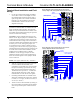
Wiring Diagram of the Terminal Block to the Feed and
Load(s) (Single-wide and Left Side Double-wide Enclosures)
TO
LOAD
4
TO
LOAD
3
TO
LOAD
2
TO
LOAD
1
HOT 1 (*)
HOT 2 (*)
HOT 3 (*)
HOT 4 (*)
NEUTRAL
NEUTRAL
NEUTRAL
NEUTRAL
GROUNDING
TERMINAL
BLOCK
GND
TERMINAL
BLOCK
LEFT
SIDE
WIRING
LABEL
AREA FOR
MODULE
LOCATION
LABEL
BYPASS
JUMPERS
(*) FROM 10 OR 16 AMP
CIRCUIT BREAKER
1. Use the two supplied self-tapping pan Phillips
screws (8B x ¼-inch (6 mm) length) to secure
the terminal block and the appropriate (left or
right) wiring label to the Crestron Automation
Enclosure. The wiring label lies beneath the
terminal block as shown in the two wiring
diagrams on this page.
NOTE: Both left and right wiring labels are
provided. The left-side labels are common for both
single and double-wide enclosures. The right-side
labels are only used in double-wide enclosures since
the modules and terminal blocks along the right side
must be inverted when mounting.
CAUTION: On this terminal block there are four
distinct circuits. Bypass jumpers are installed on the
on the brown and red sections of each circuit on the
terminal block to allow testing of the circuits and to
protect the module during installation. When properly
secured by two screws, each bypass jumper on a
circuit shorts the hot to switch so that the circuit is
receiving power. Do not remove any bypass jumpers
until all feed and load wiring has been completed, the
circuit has been tested for electrical faults, and the
module has been installed. Refer to “Module
Installation” on the next page. Jumpers are also
installed on the blue sections of the terminal block
and tie the neutrals together. These jumpers should
never be removed.
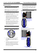
Wiring Diagram of the Terminal Block to the Feed and
Load(s) (Right Side Double-wide Enclosures)
TO
LOAD
1
TO
LOAD
2
TO
LOAD
3
TO
LOAD
4
HOT 1 (*)
HOT 2 (*)
HOT 3 (*)
HOT 4 (*)
NEUTRAL
NEUTRAL
NEUTRAL
NEUTRAL
GROUNDING
TERMINAL
BLOCK
GND
TERMINAL
BLOCK
RIGHT
SIDE
WIRING
LABEL
AREA FOR
MODULE
LOCATION
LABEL
BYPASS
JUMPERS
(*) FROM 10 OR 16 AMP
CIRCUIT BREAKER
NOTE: Use copper conductors only – rated 75°C
2. With the circuit breaker turned off, connect the
circuit feed (HOT and NEUTRAL) and
controlled circuit (LOAD) wires to the terminal
block per the markings provided on the wiring
label (as shown in the diagrams on this page).
Terminal blocks accept one 2.5 - 6.0 mm
2
wire.
Wires should be stripped to 12 mm. Tighten
terminal blocks to 1 Nm. Do not over tighten.
3. Grounding terminal blocks are available in the
cabinet for termination of ground wires. Tighten
to 4 Nm (2.5 - 6.0 mm
2
), 4.5 Nm (10.0 mm
2
), or
5.1 Nm (16 - 25 mm
2
).
4. Test the circuit for electrical faults by turning on
the circuit breaker and checking that the breaker
does not trip and that power is delivered to the
loads.
2 • Terminal Block & Module: CLTI- & CLXI-4HSW4 Installation Guide – DOC. 6412