CRESTRON CNSNET PC Interface TABLE OF CONTENTS DESCRIPTION............................................................................................................................1 Functional Description..................................................................................................1 CNSNET..............................................................................................................1 VisionPC/Control Software.............................................................
CRESTRON CNSNET PC Interface DESCRIPTION: Functional Description CNSNET The CNSNET, illustrated in figure 1, is an RS-232 interface, designed to operate with the CRESNET II remote control system (herein referred to as the CRESNET II system). This unit in conjunction with VisionPC/Control SM software permits a PC to functionally operate as a touchpanel. 1.4 in 3.7 cm CRESTRON PWR R S 232 24 Y Z G ID SEL 3.6 in 9.2 cm CNSNET 7.1 in 17.9 cm Figure 1.
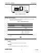
R S 232 24 Y Z G CRESTRON PWR PC Interface ID SEL CRESTRON CNSNET CNSNET Figure 2. CNSNET, Panel View LEADING SPECIFICATIONS: Table 1 provides a summary of leading specifications for the CNSNET. Dimensions and weight are approximations rounded to the nearest tenth unit. Table 1. Leading Specifications SPECIFICATION DETAILS Power Requirements CRESNET II Workshop CRESNET II Operating System 3 Watts Version 4.31 (standard released version) 3.09.17 or later (standard manufacturing version) 3.06.
CRESTRON CNSNET PC Interface ID SEL The red LED illuminates when communication between the CRESNET II system and the CNSNET is established. Illumination indicates that the identity code of the CNSNET matches the identity code of a network unit in the SIMPL program currently running in the CRESNET II system. PWR The green LED illuminates when 24 volts is supplied to the CNSNET over the network.
CRESTRON CNSNET 9. PC Interface From the "Project Install" dialog box, enter or select the project directory. The suggested directory is the same directory used earlier to install VisionPC/Control. 10. The "Project Install" dialog box also offers the opportunity for last minute verification or modification of COM port and network ID settings. 11. The program prompts the user for additional disks, as required. 12. Installation is complete. Select the OK button to return to the Program Manager window.
CRESTRON CNSNET PC Interface RJ11 DB9F 1 1 2 2 3 3 4 4 5 5 6 6 7 8 9 Figure 4. CNSNET, RJ11 RS-232 Port to 9-Pin Computer Port Cable PROGRAMMING: A basic touchpanel SIMPL program is illustrated in figure 5. An example follows the figure to illustrate the CRESNET II screen displays for touchpanel signal name assignment. The screen displays illustrated in this example are accessible from the "Define Network" section of the SIMPL-I Menu in the CRESNET II Workshop.
CRESTRON CNSNET PC Interface System PF: 4.5 Net ID Net Device 03: CTP-3000 Net PF: Description 3.0 P.F. 04: 05: 06: 07: 08: 09: 0A: TAB to select entries PgUp/PgDn to find ID F2-Detail F3-Display Signals ESC to Def Equip Net ID: Define Network F1=Help 03 CTP-3000 Command Center Touch Panel JOIN# BUTTON SIGNAL NAMES 1: relay1 P.F.: 3.0 FEEDBACK SIGNAL NAMES relay1_fb 2: relay2 relay2_fb 3: relay3 relay3_fb 4: relay4 relay4_fb 5: 6: 7: 8: 10. m 11.
CRESTRON CNSNET PC Interface TEST/TROUBLESHOOTING: Table 2 provides corrective action for possible trouble situations. If further assistance is required, please contact a CRESTRON technical support representative. Table 2. Troubleshooting Guide TROUBLE POSSIBLE CAUSE(S) CNSNET does not function. CNSNET is not communicating to the network. NET PWR LED is not illuminated. CNSNET is not receiving network power. Incorrect network wiring. CNSNET is not responding.
CRESTRON CNSNET PC Interface SYNTAX: The following syntax codes are provided for compatibility purposes only. NET.
CRESTRON CNSNET PC Interface CRESNET II Limited Warranty CRESTRON ELECTRONICS, Inc. warrants its CRESNET II products, denoted by a "CN" prefix model number, to be free from manufacturing defects in materials and workmanship for a period of three (3) years from the date of shipment to purchaser. Disk drives and any other moving or rotating mechanical parts are covered for a period of one (1) year, excluding switches and pushbuttons, which are covered for three (3) years.